Make Holiday Projects React to Light
A light sensor can add interactivity to your artwork by making it react to the presence or absence of light.
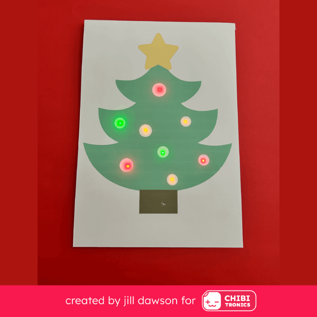
In this post, I’ll show you how to use a Chibitronics Light Sensor Sticker to make a light-sensing tree with Chibitronics Launchpad LEDs. We’ll add a bit of light-reactive magic — without coding!
While the Chibitronics Light Sensor Sticker is commonly used with our Creative Coding resources (including the Chibi Chip), this sensor is actually quite versatile! This means that it can be used with or without a microcontroller.
Learn Light Sensor Basics
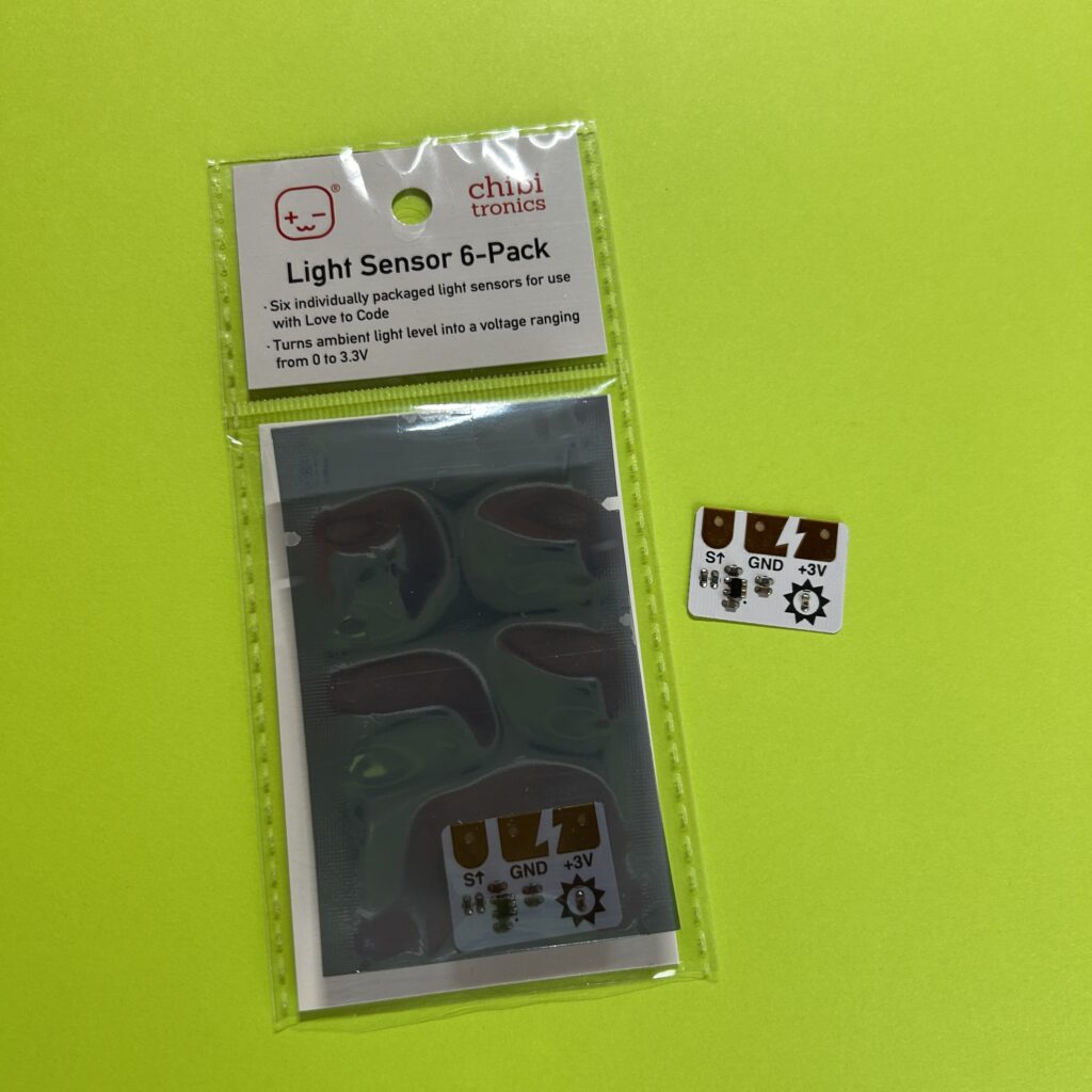
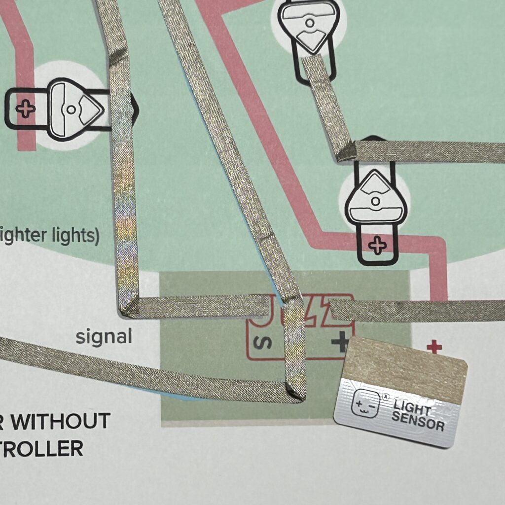
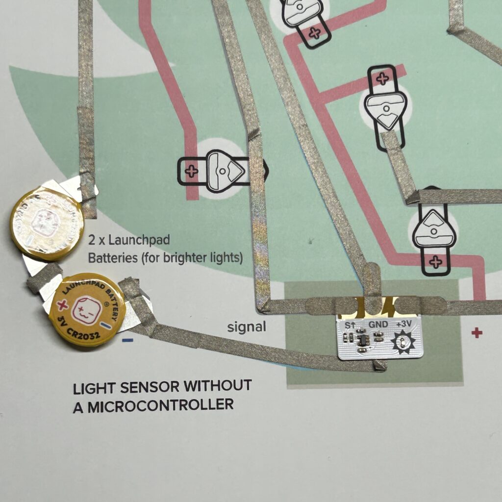
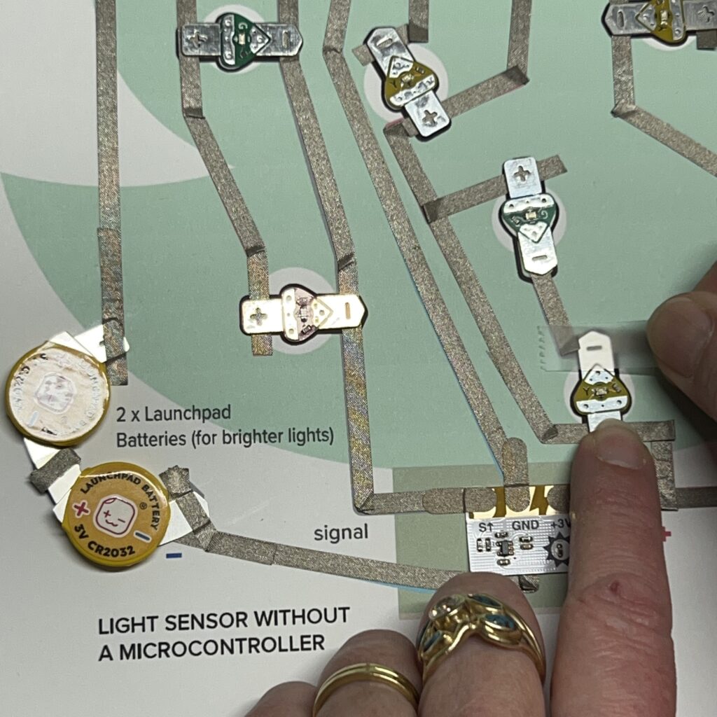
The Light Sensor Sticker has three metal pads — SIGNAL (S↑), GND (-), and POSITIVE (+3V).
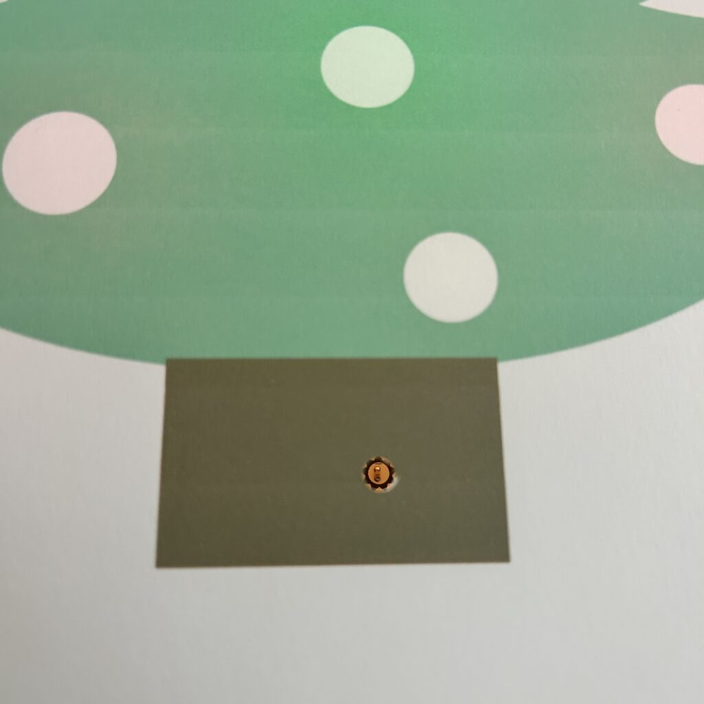
The part of the sticker that actually detects light, the sensor itself, is encircled within a symbol of the sun.
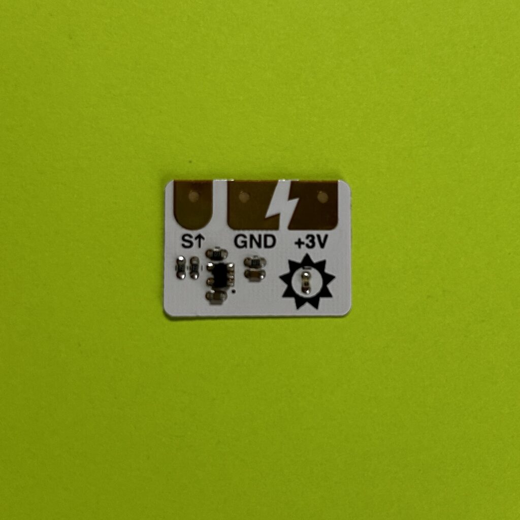
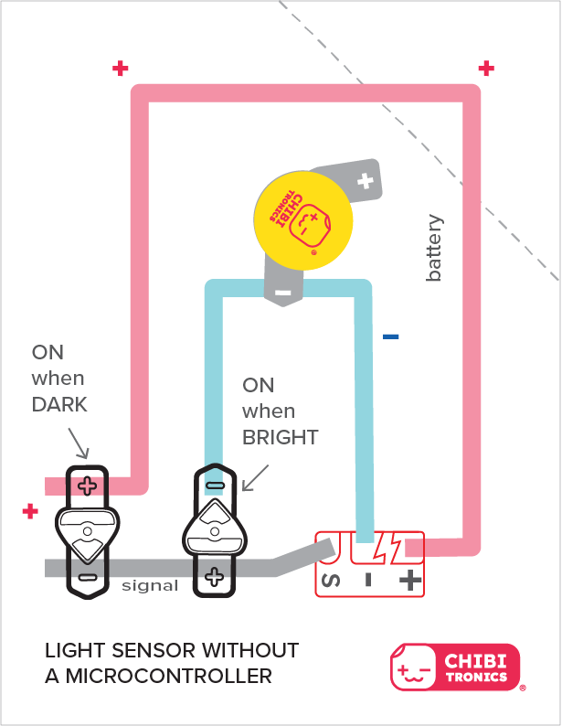
As the sensor detects different levels of light, varying amounts of power are delivered to the circuit through the SIGNAL (S↑) pad. Then, depending upon the orientation of the LEDs within the circuit, they will either turn on or turn off when the sensor detects brightness or darkness.
In some ambient settings (between darkness and light) it is also possible that all of the LEDs may turn on at once, while at other times they may all turn off.
Learn How to Use a Chibitronics Light Sensor Without a Microcontroller
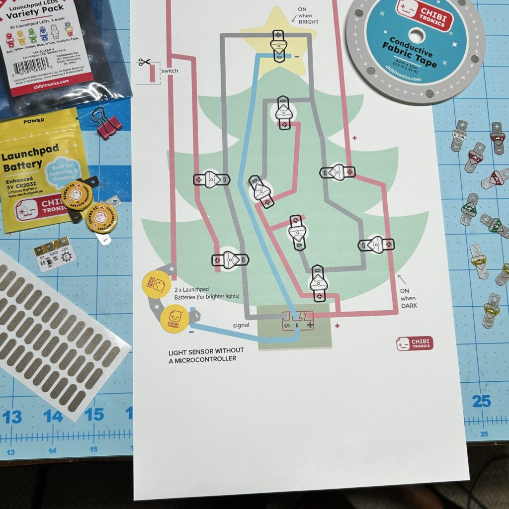
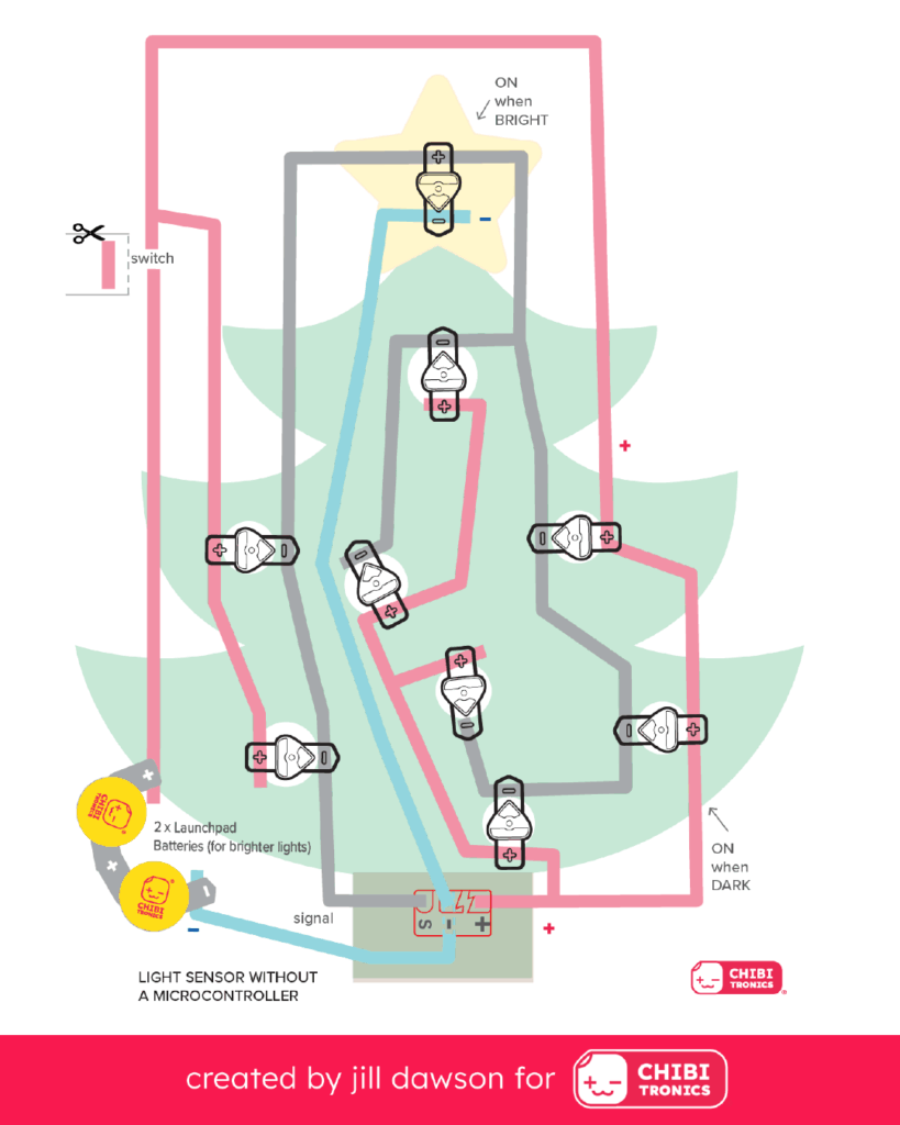
If you’d like to experiment before building an actual project, download and print out this sheet of Circuit Diagrams. The top two circuit diagrams use Circuit Sticker LEDs, while the bottom two use Launchpad LEDs.
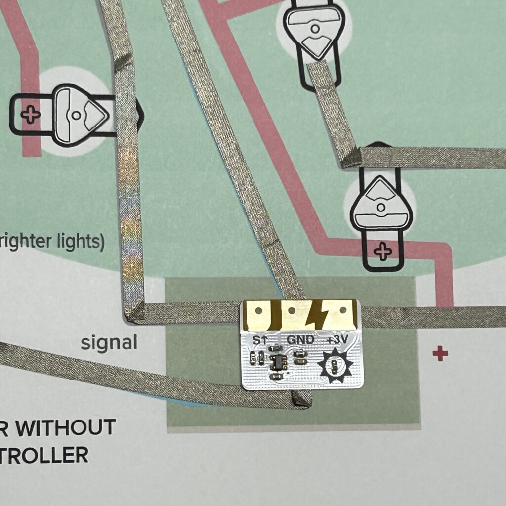
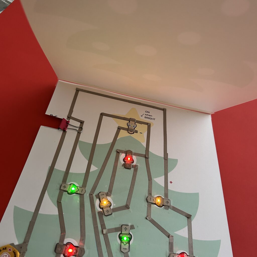
In the example below, two Launchpad LEDs have been connected to a Light Sensor Sticker to showcase how they each respond to different light conditions. You do not have to include LEDs for both conditions, however, and the sensor will still work.
I used non-conductive Scotch tape to adhere the Launchpad LEDs on top of the Conductive Fabric Tape traces, but you may also use Conductive Fabric Tape to do this.
I suggest that you leave the protective backing on the back of the Light Sensor Sticker and use Conductive Fabric Tape Patches (or scraps of Conductive Fabric Tape) to connect it to the circuit. That way, you can easily remove and reuse the sensor.
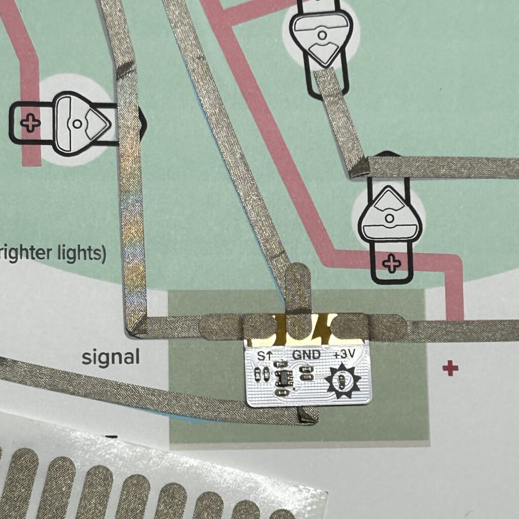
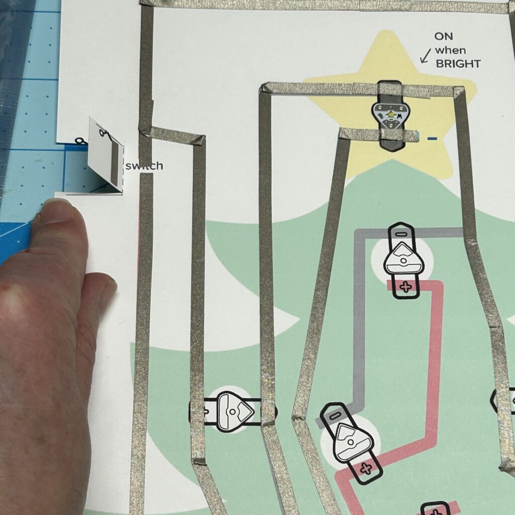
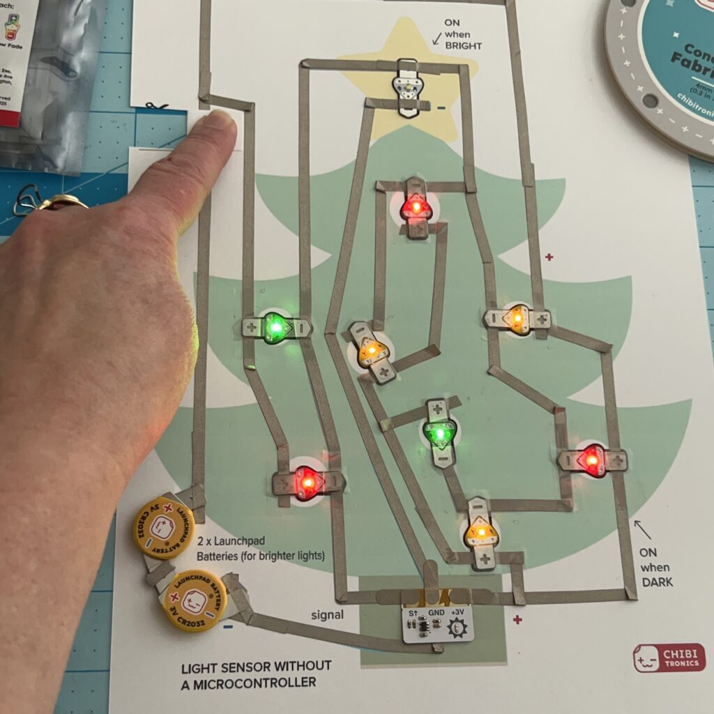
In the example below, two Launchpad LEDs have been connected to a Light Sensor Sticker, and a switch has been added to allow you to easily disconnect the circuit from power. Like the previous example, you do not have to include LEDs for both conditions, and you can also modify how many LEDs you actually use for each.
When applying the negative (-) trace that connects to the battery, be sure to use a continuous piece of Conductive Fabric Tape that extends underneath the Light Sensor Sticker. Secure the sensor in place with Conductive Fabric Tape Patches .
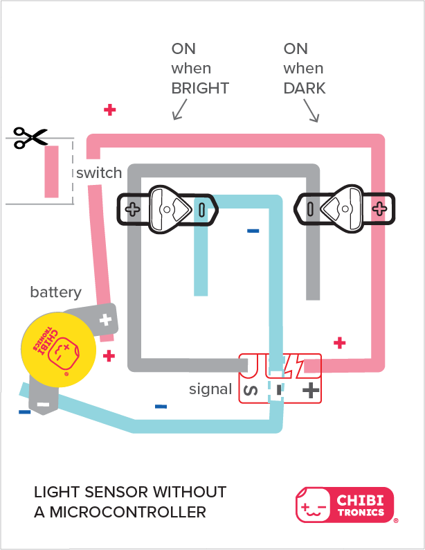
Tips, Tricks, and Trade-Offs: While it’s okay to leave your circuit connected to the Launchpad Battery when you wish to observe changes to your artwork’s appearance at different times of day, disconnecting power while your artwork is unattended will help conserve battery life. This is a power-hungry circuit!
Light Sensor Quick Reference Guide
(To help you understand how the connections work)
| Light is ON when it’s DARK | Light is ON when it’s BRIGHT |
| Connect the SIGNAL (S↑) pad of the sensor with the GROUND (-) end of an Launchpad LED/ LED Sticker. | Connect the SIGNAL (S↑) pad of the sensor with the POSITIVE (+) end of an Launchpad LED/ LED Sticker. |
| Connect the GROUND (GND) pad of the sensor with the negative pad of a Launchpad Battery. | Connect the GROUND (GND) pad of the sensor with the negative pad of a Launchpad Battery and the negative pad of a Launchpad LED/ LED Sticker. |
| Connect the POSITIVE (+3V) pad of the sensor with the positive pad of a Launchpad Battery and the positive end of a Launchpad LED/ LED Sticker. | Connect the POSITIVE (+3V) pad of the sensor with the positive pad of a Launchpad Battery. |
Make a Light-Sensing Christmas Tree
Useful Tools & Supplies
- Launchpad LEDs or Circuit Sticker LEDs of your choice.
- I used colorful LEDs from a Launchpad LED Variety Pack
- Conductive Fabric Tape or Conductive Copper Tape
- Conductive Fabric Tape Patches (optional, but useful)
- Sticky Scotch Tape
- 2 x 3V Launchpad Batteries
- 1 x small binder clip
- Printer (for printing out the Circuit Diagrams or Templates)
- White Cardstock (8″ x 10″)
- Scissors
- Hole Punch or Japanese Screw Punch
Directions
Step 1: Download & Print Templates
The first step is to download and print the templates onto white cardstock. I’ve included a Christmas Tree Top Layer and Christmas Tree Circuit Diagram bottom layer.
To make the art layer, I modified a Public Domain Christmas Tree Vector that I found at SVGREPO, but you might want to create your own original design.
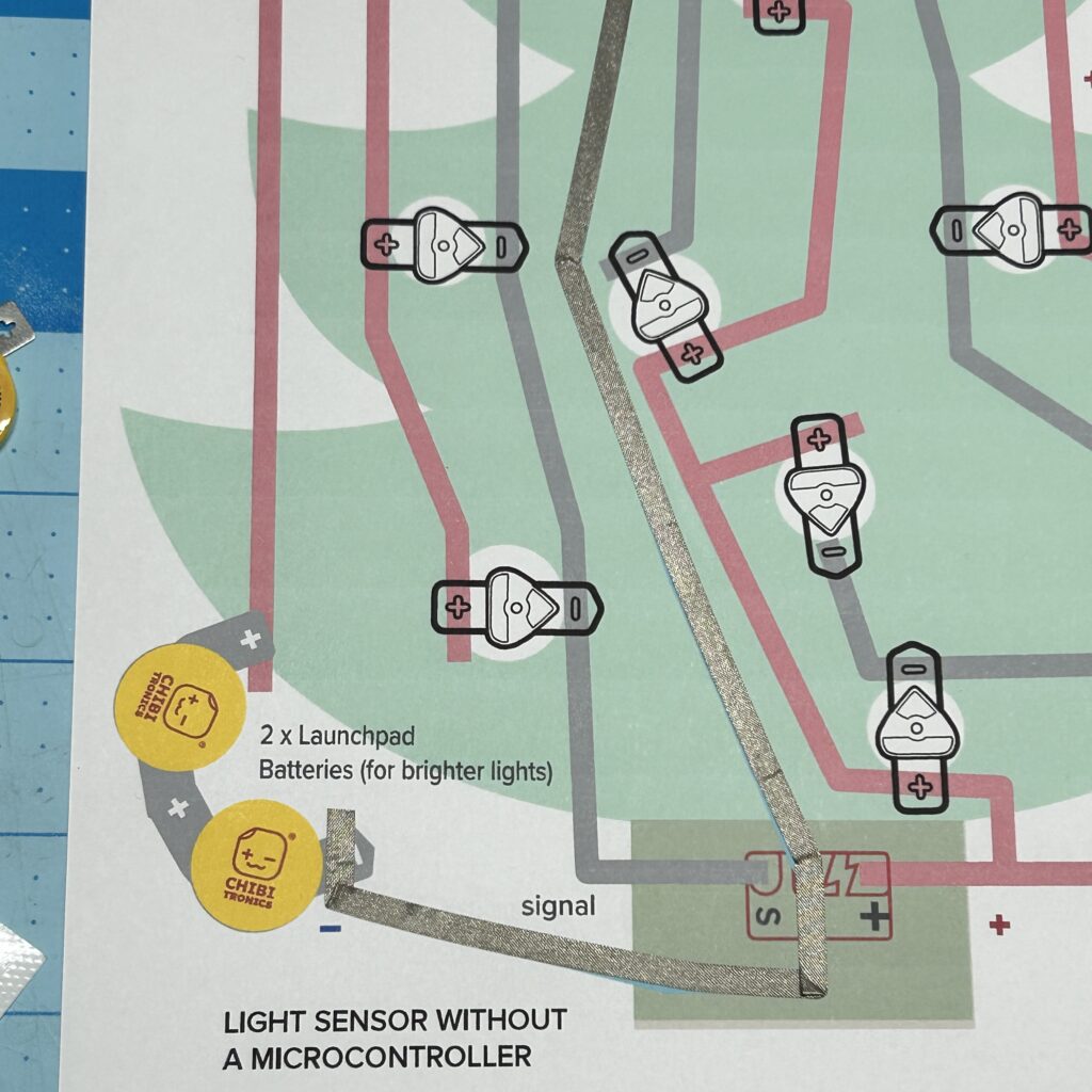
Step 2: Lay Down Conductive Fabric Tape
The next step is to start applying Conductive Fabric Tape to the Circuit Diagram, starting with the blue, negative (-) trace at the bottom. Use a continuous piece of Conductive Fabric Tape; there should not be a gap in it, where the Light Sensor will be adhered.
Continue adding Conductive Fabric Tape to the pink, positive (+) trace and the grey, Signal (S↑) traces.
Step 3: Secure Light Sensor
After you’ve added Conductive Fabric Tape to the Light Sensor footprint on the template, use Conductive Fabric Tape Patches (or scraps) to connect the metal pads on the Light Sensor to those conductive traces.
Leave the protective backing on the Light Sensor Sticker, so you can easily remove and reuse it in another project.
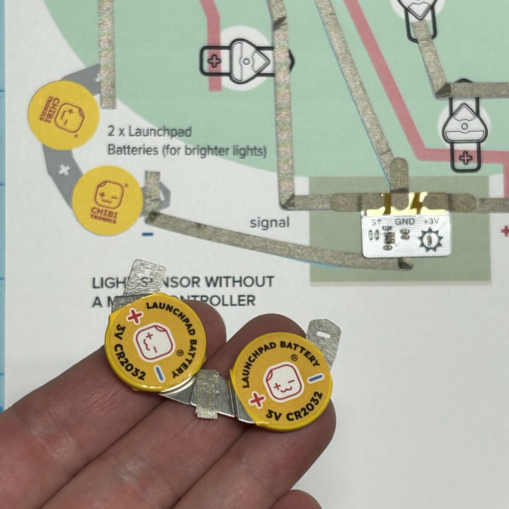
Step 4: Connect Launchpad Batteries in Series
After you’ve connected the Light Sensor, connect two Launchpad Batteries in series, by overlapping the negative pad of one battery on top of the positive pad of a second battery. Secure the overlapped pads with either Conductive Fabric Tape or Scotch Tape. The pads need to stay connected in order for power to flow through the circuit.
Then, tape the the two batteries into the circuit. Secure the positive (+) pad to the positive (+) trace and the negative (-) pad to the negative (-) trace. I used Conductive Fabric Tape in the images below, but Scotch tape may also be used for this purpose. Whatever tape you use, it’s important to ensure a secure physical connection.
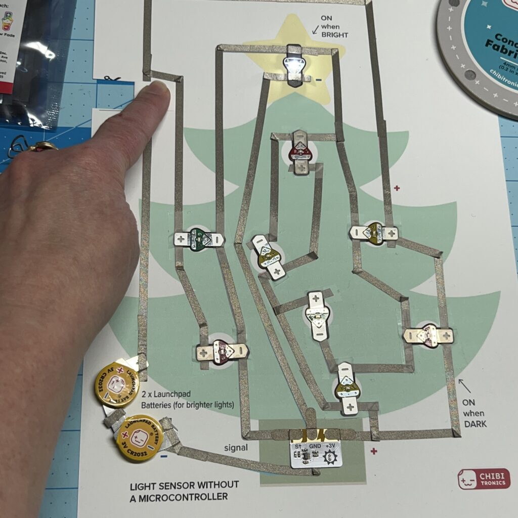
Step 5: Prep the Switch & Test the Circuit
Once the Launchpad Batteries are secured, cut, fold, and adhere Conductive Fabric Tape to the switch flap.
Then, secure a Launchpad LED to the footprint inside of the star, using either Conductive Fabric Tape or Scotch tape.
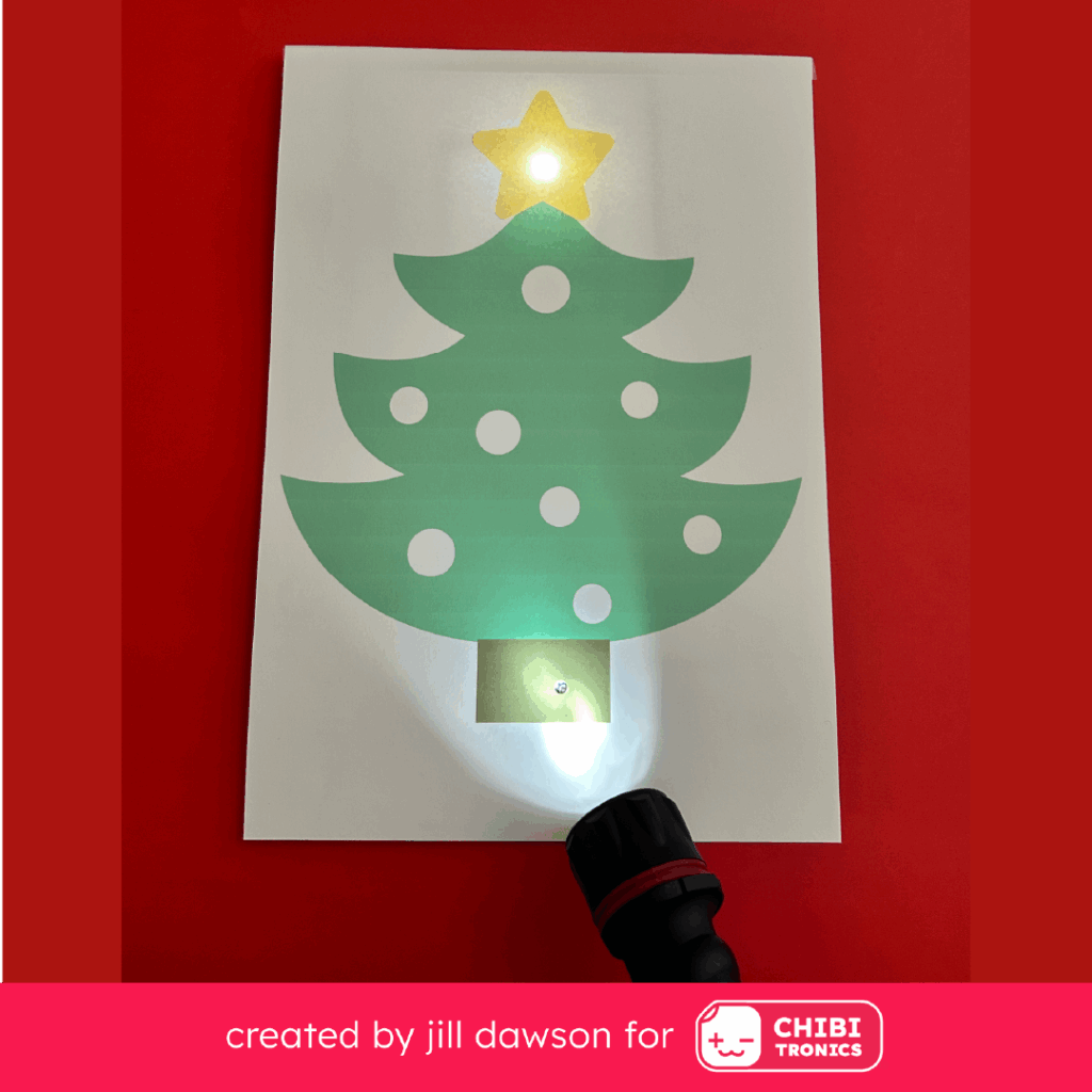
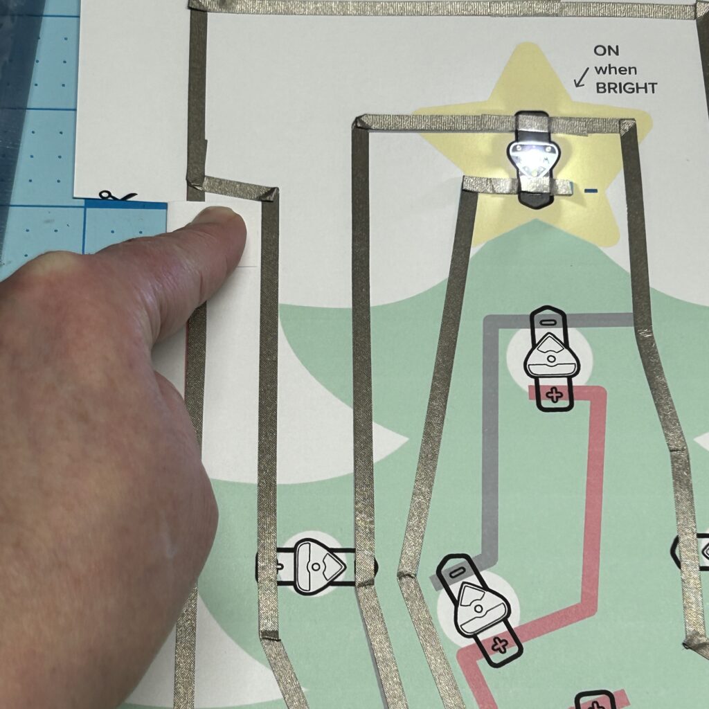
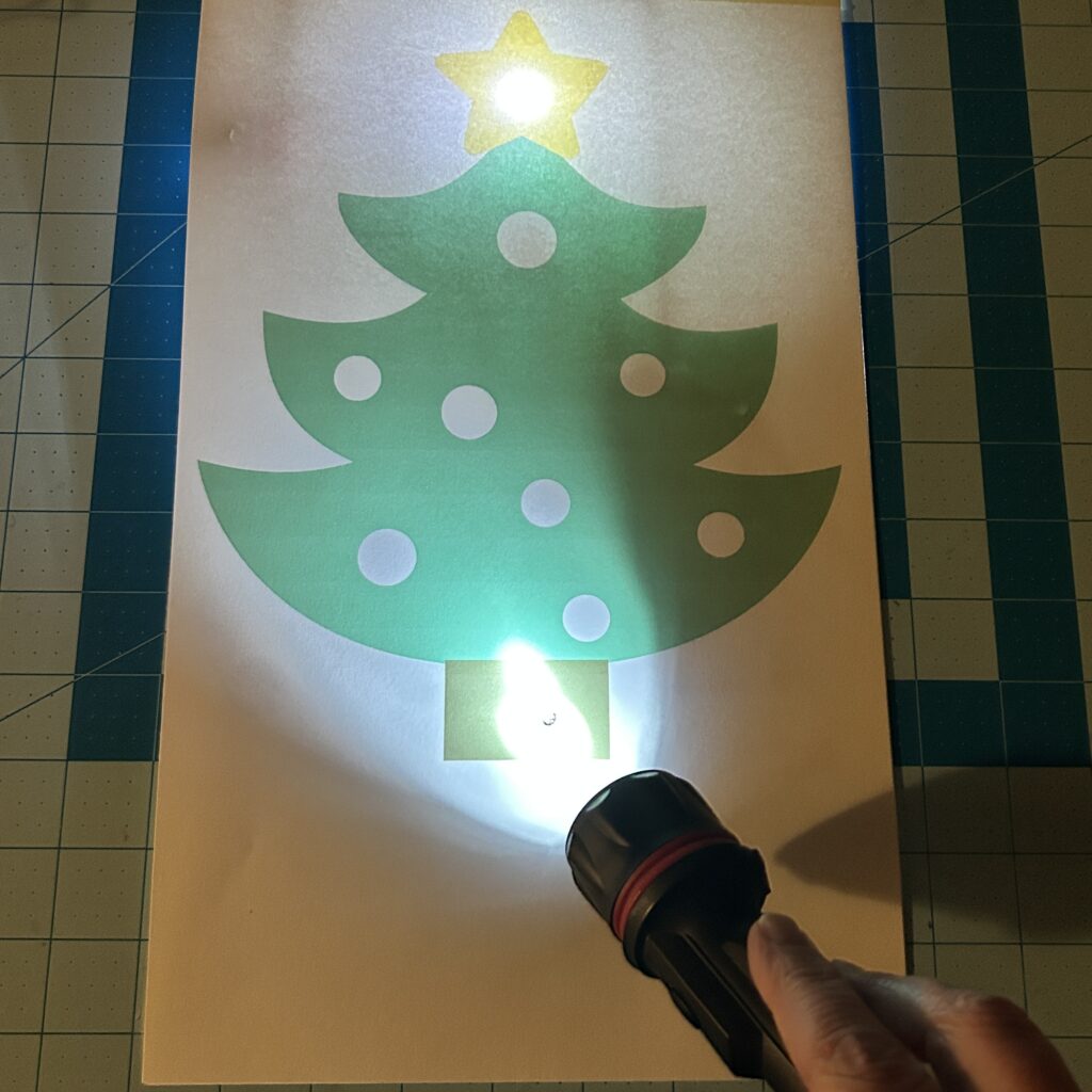
Expose the Light Sensor to light and hold down the switch. It should turn on.
Step 6: Add Launchpad LEDs
Finish applying Conductive Fabric Tape to the rest of the Circuit Template. Add Launchpad LEDs. Secure them with either Conductive Fabric Tape or Scotch tape.
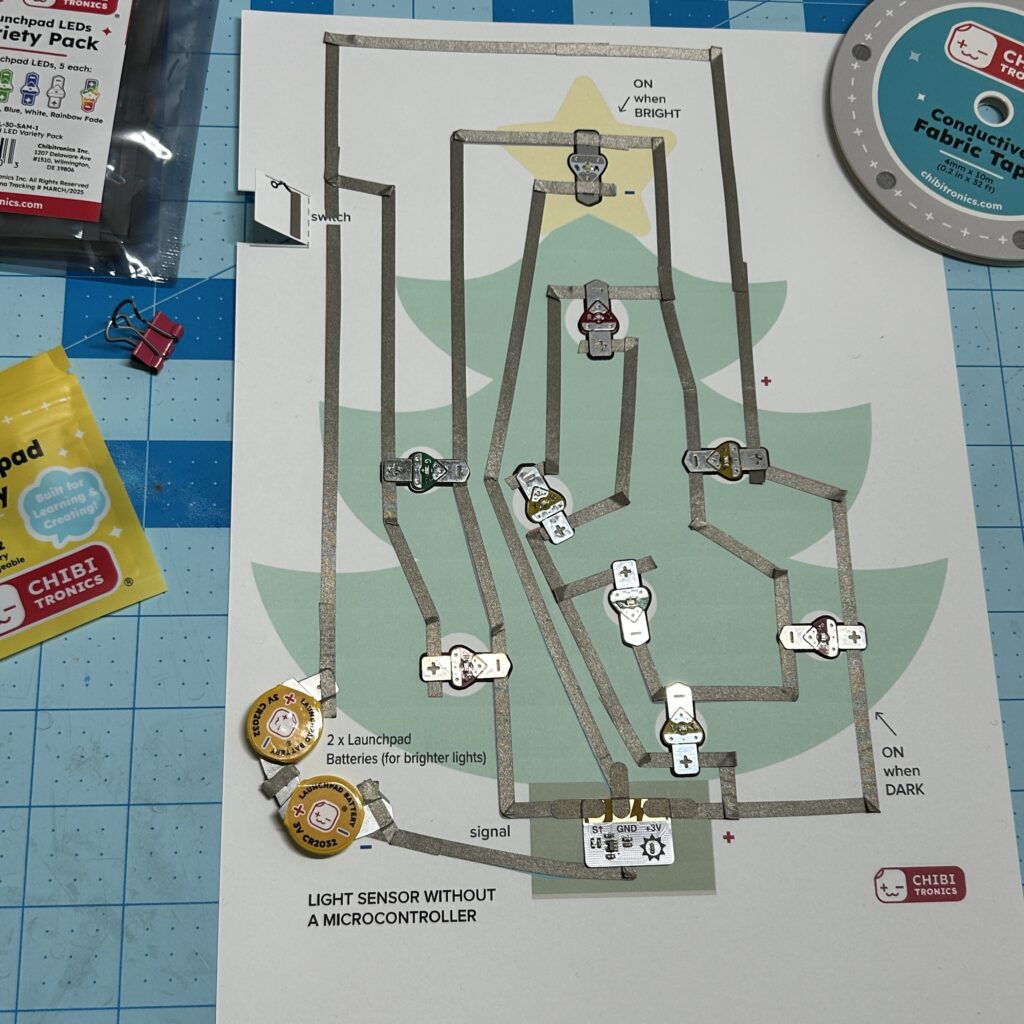
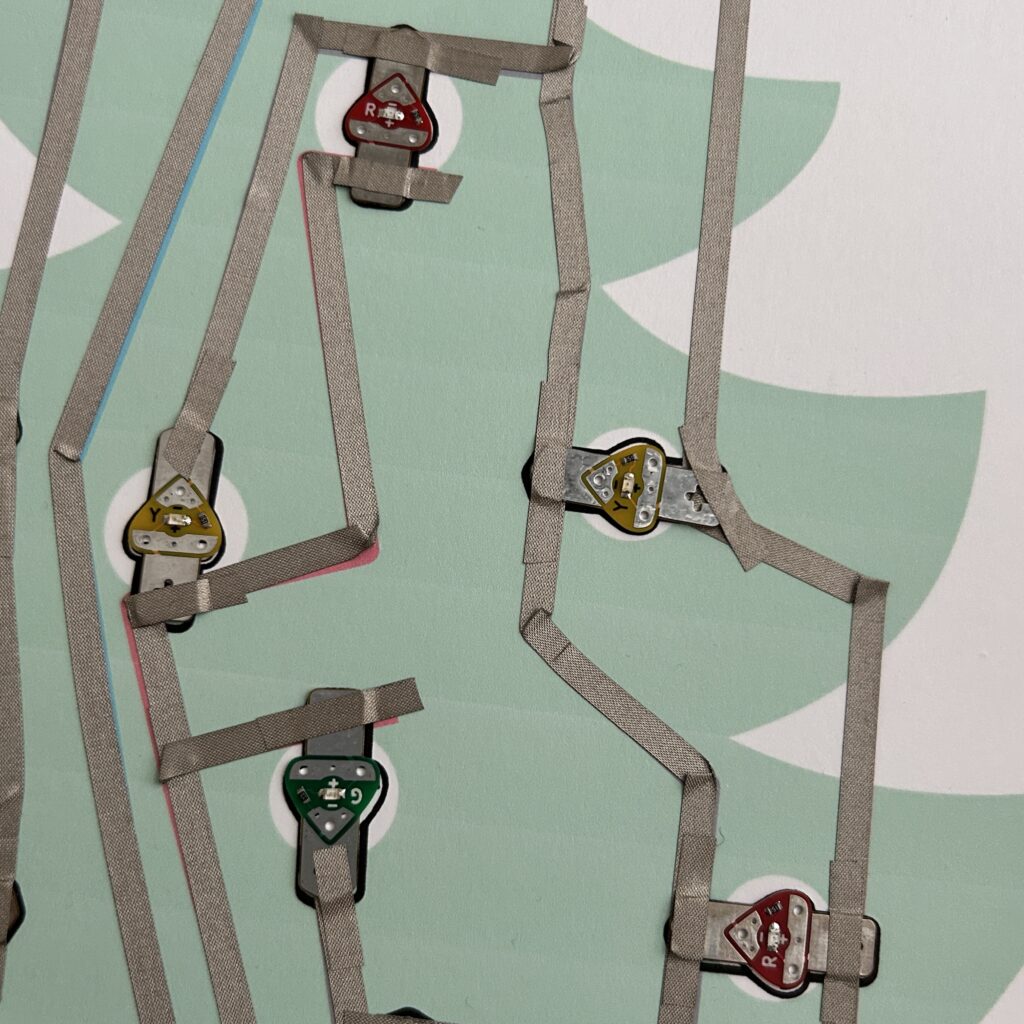
If you use Conductive Fabric Tape to connect the Launchpad LEDs to the circuit traces, be sure to use a fingernail (or another tool) around the edges to ensure that the connections are secure.
Using pieces of Conductive Fabric Tape that are too short can result in connections that come loose.
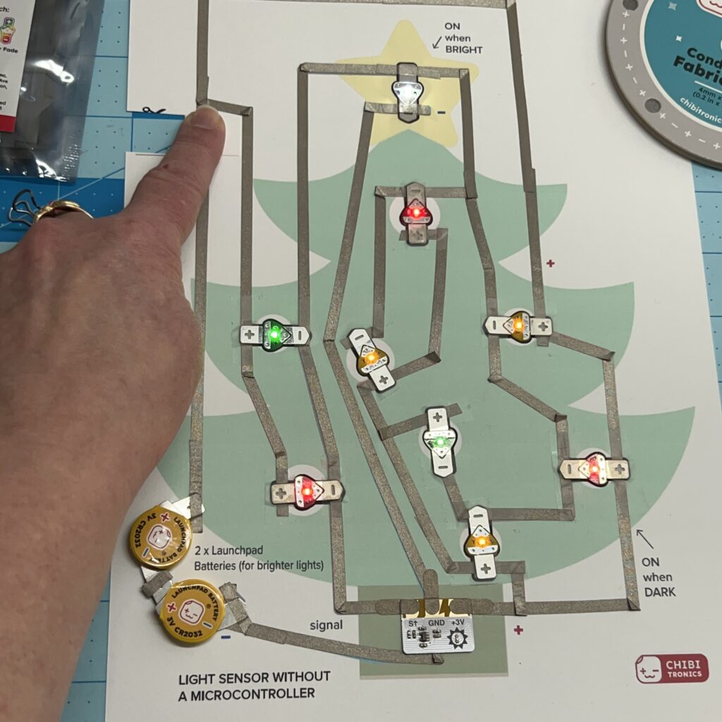
Step 7: Test the Circuit Again
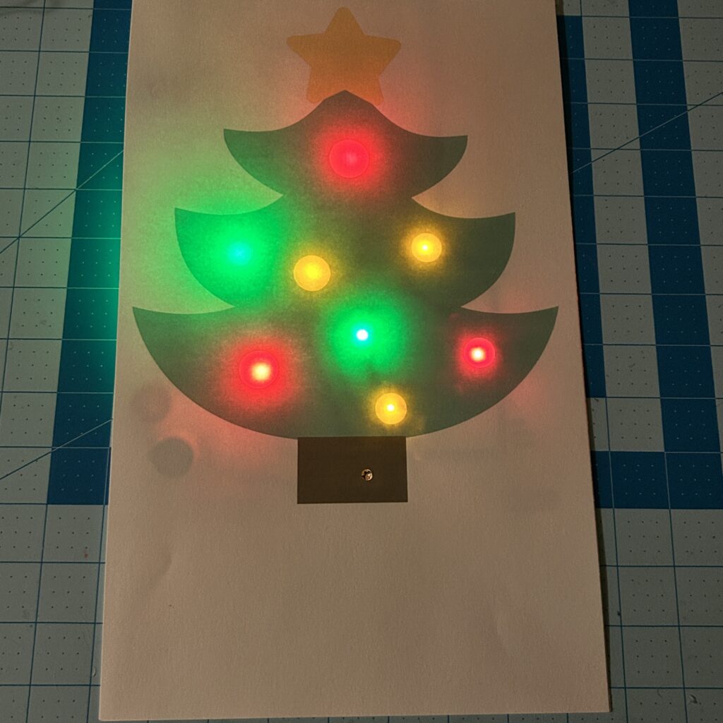
Once you’ve connected the rest of the Launchpad LEDs to the template, test the circuit again under different light conditions.
Step 8: Tape Art Layer to Circuit Layer
Once you’ve confirmed that your circuit is working properly, adhere the art layer to the circuit layer. I created a hinge at the top with a piece of Scotch tape.
Lastly, use a hole punch to add a hole to the art layer for the Light Sensor.
Learn How to Use a Light Sensor With a Microcontroller
The Chibitronics Light Sensor Sticker is most commonly used in a classroom setting, to help students learn the difference between traditional on/off switches and programmable sensors that can read and respond to a range of analog data points.
To learn more about how to use our Light Sensor with a microcontroller, visit Light Sensor | Chibitronics.