Create Projects That React to Light!

Did you know that a light sensor can add interactivity to your artwork by making it react to the presence or absence of light? Did you know that the Chibitronics Light Sensor Sticker can be used with or without a microcontroller?
While both the Chibitronics Light Sensor Bundle and Light Sensor Materials Kit are typically used in conjunction with our Creative Coding resources (including the Chibi Chip), the Light Sensor Sticker is actually quite versatile!
In this post, I’ll show you how to use a Light Sensor Sticker in a battery-powered paper circuit project (no microcontroller), to add a bit of light-reactive magic to your art!
Light Sensor Basics
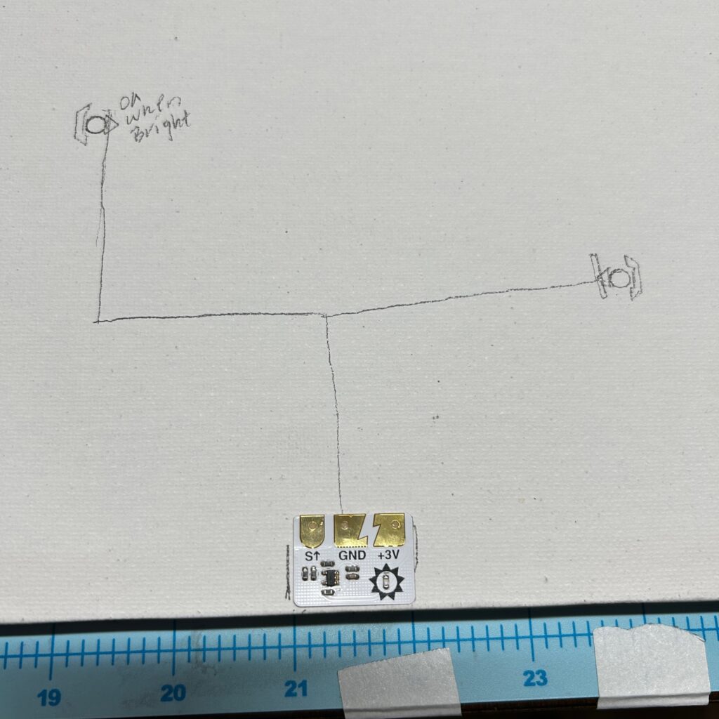
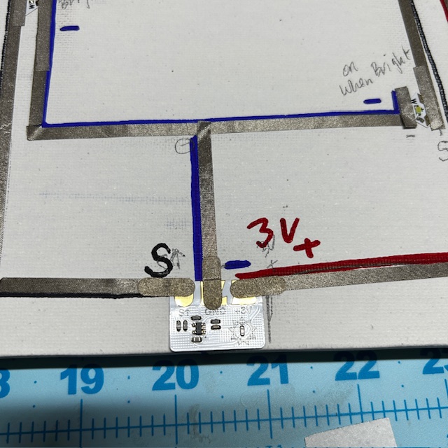
The Light Sensor Sticker has three metal pads — SIGNAL (S↑), GND (-), and POSITIVE (+3V).
The sensor, itself, is denoted with the symbol of the sun. This part of the sticker detects light.
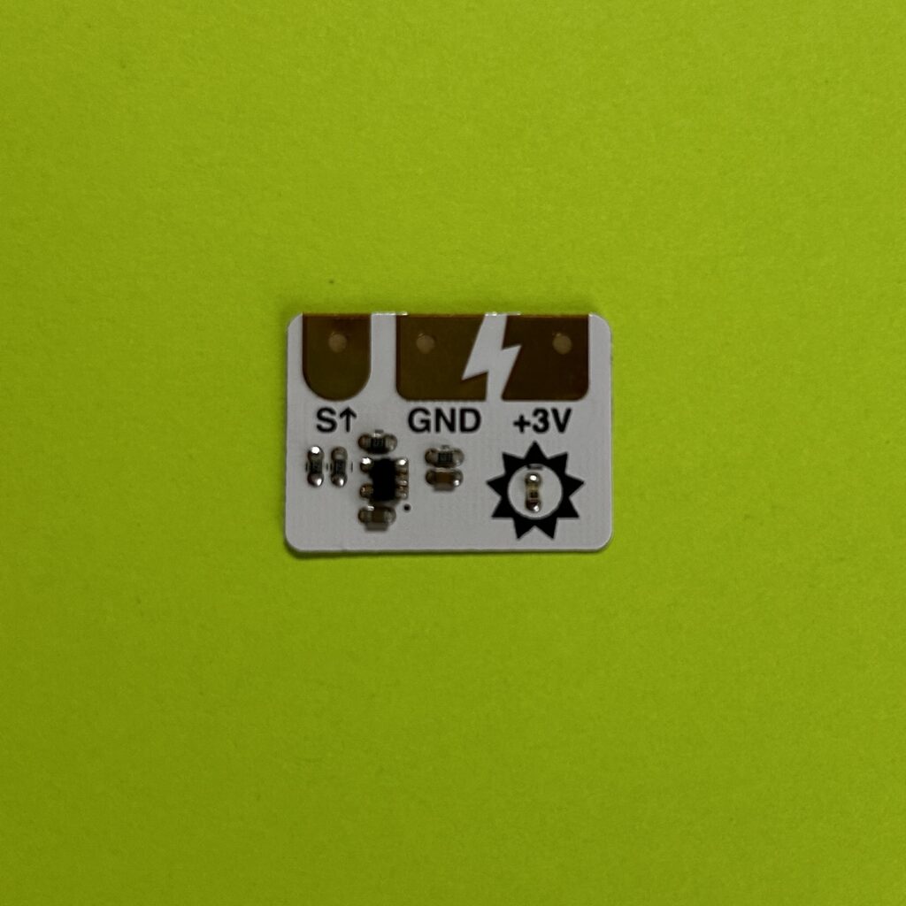
As the sensor detects different levels of light, varying amounts of power are delivered to the circuit through the SIGNAL (S↑) pad. Then, depending upon the orientation of the LEDs within the circuit, they will either glow or turn off when the sensor detects brightness or darkness. In ambient settings, the LEDs may not appear to do anything.
Learn How to Use a Chibitronics Light Sensor Without a Microcontroller
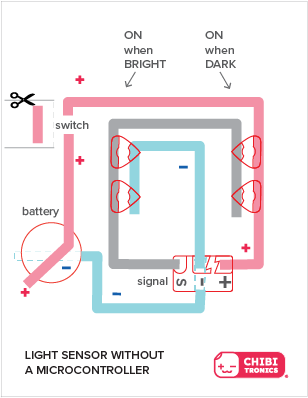
To create your own, download and print out this sheet of Circuit Diagrams.
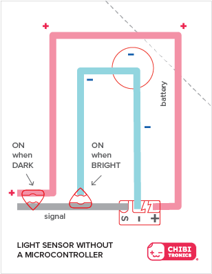
In the example below, two LEDs have been connected to a Light Sensor Sticker to showcase how they each respond to different light conditions. You do not have to include LEDs for both conditions, however, and the sensor will still work.
In the example below, two LEDs have been connected to a Light Sensor Sticker, and a switch has been added to allow you to disconnect the circuit from power. Like the previous example, you do not have to include LEDs for both conditions, and you can also modify how many LEDs you actually use for each.
Tips, Tricks, and Trade-Offs: While it’s okay to leave your circuit connected to the battery when you wish to observe changes to your artwork’s appearance at different times of day, disconnecting power while your artwork is unattended will conserve battery life. Also, while the Light Sensor Sticker may be directly adhered to the template, we suggest that you leave the protective backing on and use Conductive Fabric Tape Patches (or scraps of Conductive Fabric Tape) to connect it to the circuit. That way, you can easily remove and reuse it.
Quick Reference Guide
| Light is ON when it’s DARK | Light is ON when it’s BRIGHT |
| Connect the SIGNAL (S↑) pad of the sensor with the GROUND (-) end of an LED Sticker | Connect the SIGNAL (S↑) pad of the sensor with the POSITIVE (+) end of an LED Sticker. |
| Connect the GROUND (GND) pad of the sensor with the negative side of a battery. | Connect the GROUND (GND) pad of the sensor with the negative side of a battery and the negative end of an LED sticker. |
| Connect the POSITIVE (+3V) pad of the sensor with the positive side of a battery and the positive end of an LED Sticker. | Connect the POSITIVE (+3V) pad of the sensor with the positive side of a battery. |
How Might You Use a Light Sensor in a Project?
Light Reactive Painting

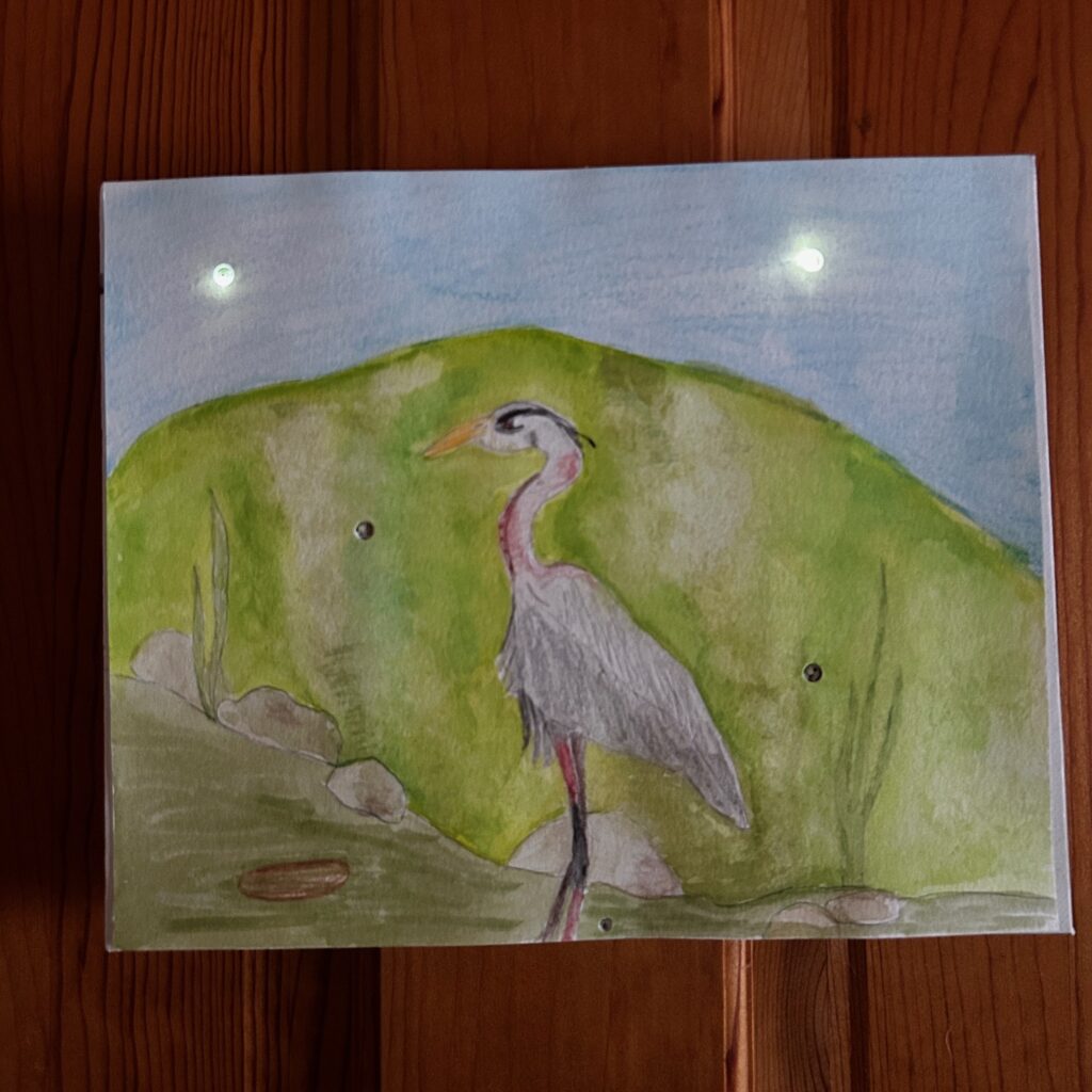
I created a light reactive painting of a heron to demonstrate a way to use the Light Sensor Sticker in a project.
Useful Tools & Supplies
- LED Circuit Stickers of your choice (I used 2 White Blink Animating LEDs and 2 White Fade Animating LEDs)
- Conductive Fabric Tape or Copper Tape
- Conductive Fabric Tape Patches (optional, but useful)
- 3V Coin Cell Battery
- Velcro dots
- Canvas frame or a sturdy piece of cardboard to mount your artwork
- Watercolor paper and paints
- Paintbrush
- Scissors
- Screw Punch
- Pencil
- Printer (if you plan to print out a circuit template to use as a reference)
Directions
- To make my project, I first sketched and painted a heron scene.


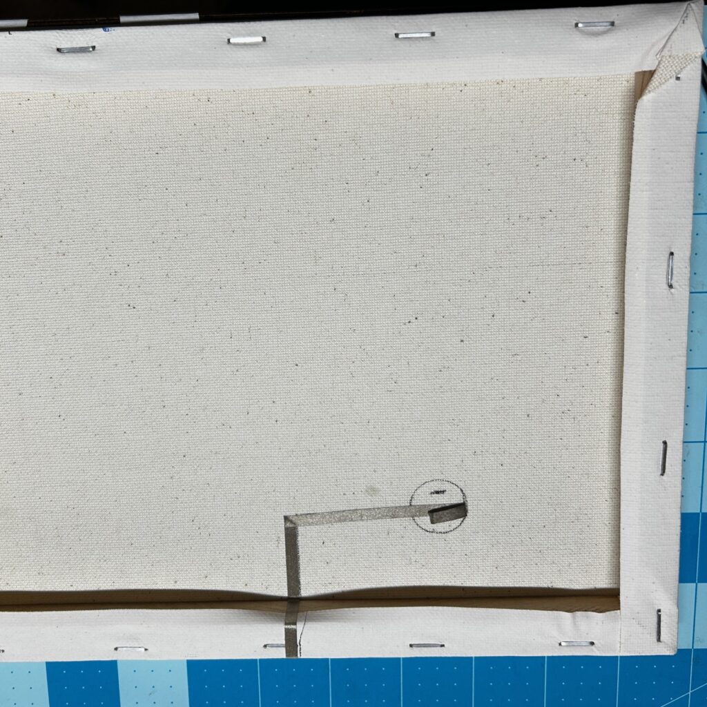
2. Next, I decided to use two LEDs in the sky to represent fireflies in the dark and two more in the water to make ripples shimmer in the sun. After figuring out their placement, I used a screw punch to make holes in the painting and a pencil to trace the holes onto my canvas.
Note: I added the hole for the Light Sensor after I completed the circuit.

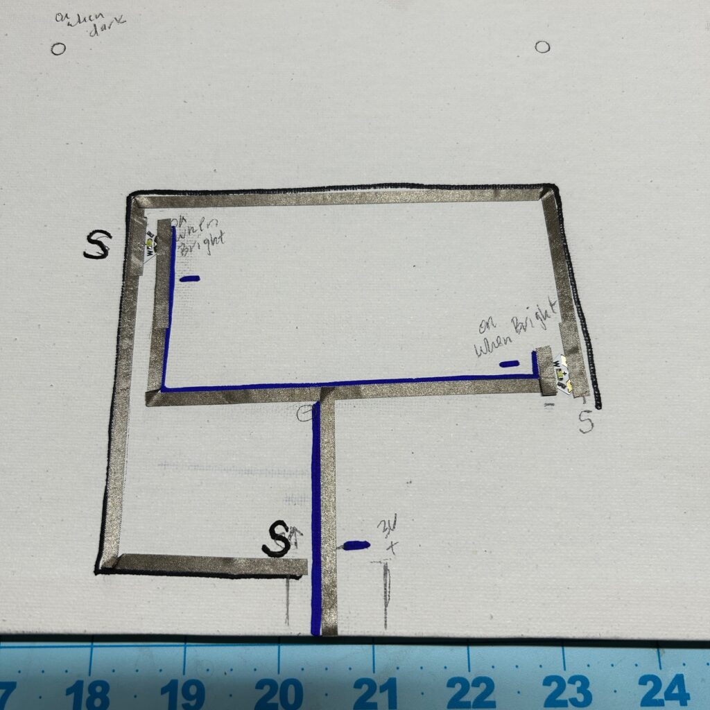
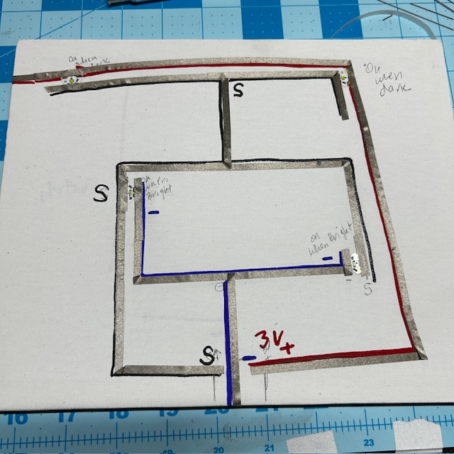
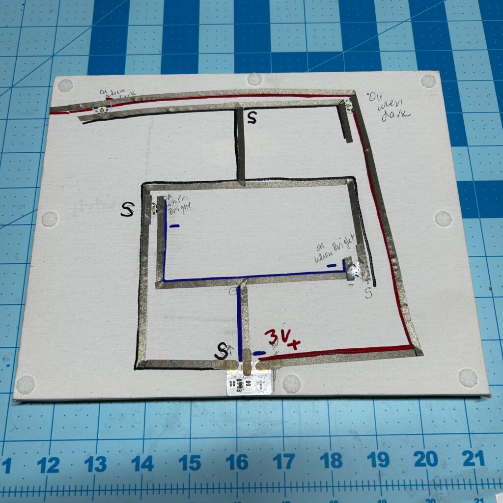
3. After sketching the locations for my LED Stickers, I used this Template as a guide to plan out my circuit, starting with the NEGATIVE trace and the two LEDs that would turn on when it’s BRIGHT. I positioned my Light Sensor at the bottom of the frame, leaving the protective backing on.
The NEGATIVE trace connects to the NEGATIVE end of the LEDs and extends from the front of the frame around to the back side, connecting to the negative side of the battery. This trace should be continuous and not have any gaps.
The GROUND pad of the light sensor will be placed on top of the NEGATIVE trace in a later step.
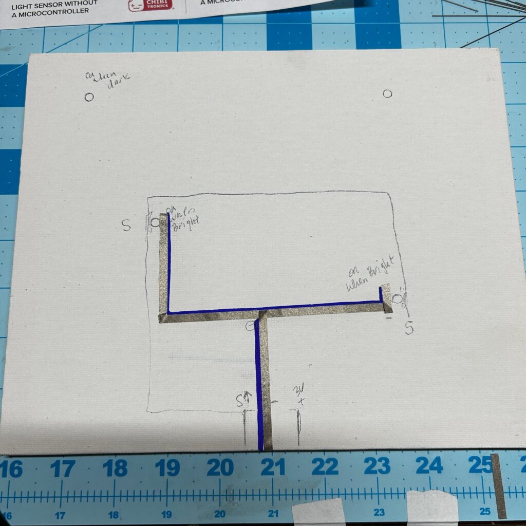
The POSITIVE ends of the LEDs connect with the SIGNAL (S↑) pad of the light sensor.
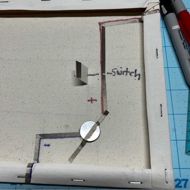
4. Next, I completed the circuit for the two LEDs that I wanted to turn on when it’s DARK. The POSITIVE trace of the circuit, which connects to the POSITIVE (+3V) pad of the Light Sensor, connects to the POSITIVE end of the stickers and wraps around to the back of the frame.
On the back of the frame, I left a gap in the POSITIVE trace to form a SWITCH, with one section of the POSITIVE trace connecting with the POSITIVE end of the LED Stickers and the other section connecting with the positive side of the battery.
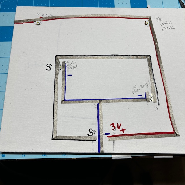
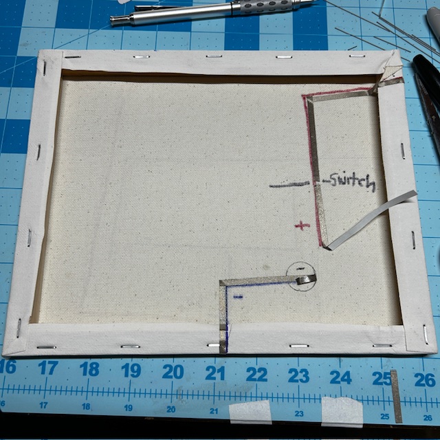
To close the gap in the switch, I used a flap of paper that I could tape closed; but, you could also just apply a patch of Conductive Fabric Tape over it.
Lastly, I extended the SIGNAL trace from the first part of the circuit, connecting it to the narrow, NEGATIVE end of the stickers.
5. I reinforced all my LEDs with Conductive Fabric Tape, attached the Light Sensor Sticker using Conductive Fabric Tape Patches, and then closed the switch to test the circuit.
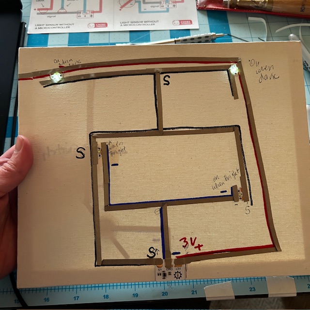
6. Once I confirmed that it was working properly, I adhered my artwork to the canvas with Velcro dots.
Other Project Ideas to Consider
- Create a piece of artwork that lights up one object when it’s light and another when it gets dark
- Create a sign for your room that lights up when it gets dark
- Create a 3D model, such as a Christmas tree or a lighthouse, that blinks on and off when a flashlight is shined upon it, using White Blink Animating LEDs)
Or, for an extra challenge, why not try adapting one of the following DIY Projects by adding a Light Sensor Sticker?
- This Nightlight Has a Secret
- How to Make Glowing Paper Circuit Lanterns with Chibitronics LED Stickers
- Make a Solar-Powered Model House with Chibitronics Circuit LED Stickers
Learn How to Use a Light Sensor With a Microcontroller
Our Light Sensor Sticker is most commonly used in a classroom setting, to help students learn the difference between traditional on/off switches and programmable sensors that can read and respond to a range of analog data points.
To learn more about how to use our Light Sensor with a microcontroller, visit Light Sensor | Chibitronics.