This tutorial will show you how to solder to circuit stickers and use the programmable microcontroller to create a ferris wheel with spining lights. The tutorial will be divided into two sections- programming your microcontroller and crafting your circuit.
You will need:
- An In System Programmer (ISP) to connect the microcontroller sticker to the computer and load your code, such as:
- Tiny AVR programmer this programmer is easiest to start with. It also has a convenient connector for easily programming bare Attiny85 microcontrollers
- AVRISP MKII this can be used to program any sort of AVR microcontroller
- Arduino as programmer If you have an Arduino handy, you can also use it as a programmer. To do so, you will first need to program your Arduino board as a programmer. Here are tutorials for turning the Arduino UNO and Arduino Leonardo into ISPs. For the Arduino UNO, you will also need a 10uF or larger capacitor.
- Microcontroller circuit sticker (in the Sensors add-on)
- Circuit sticker programming adapter (also included in the Sensors add-on)
- 6 jumper wires
- 8 LED stickers
- Copper foil tape
- 3V coin cell battery
- Binder clip
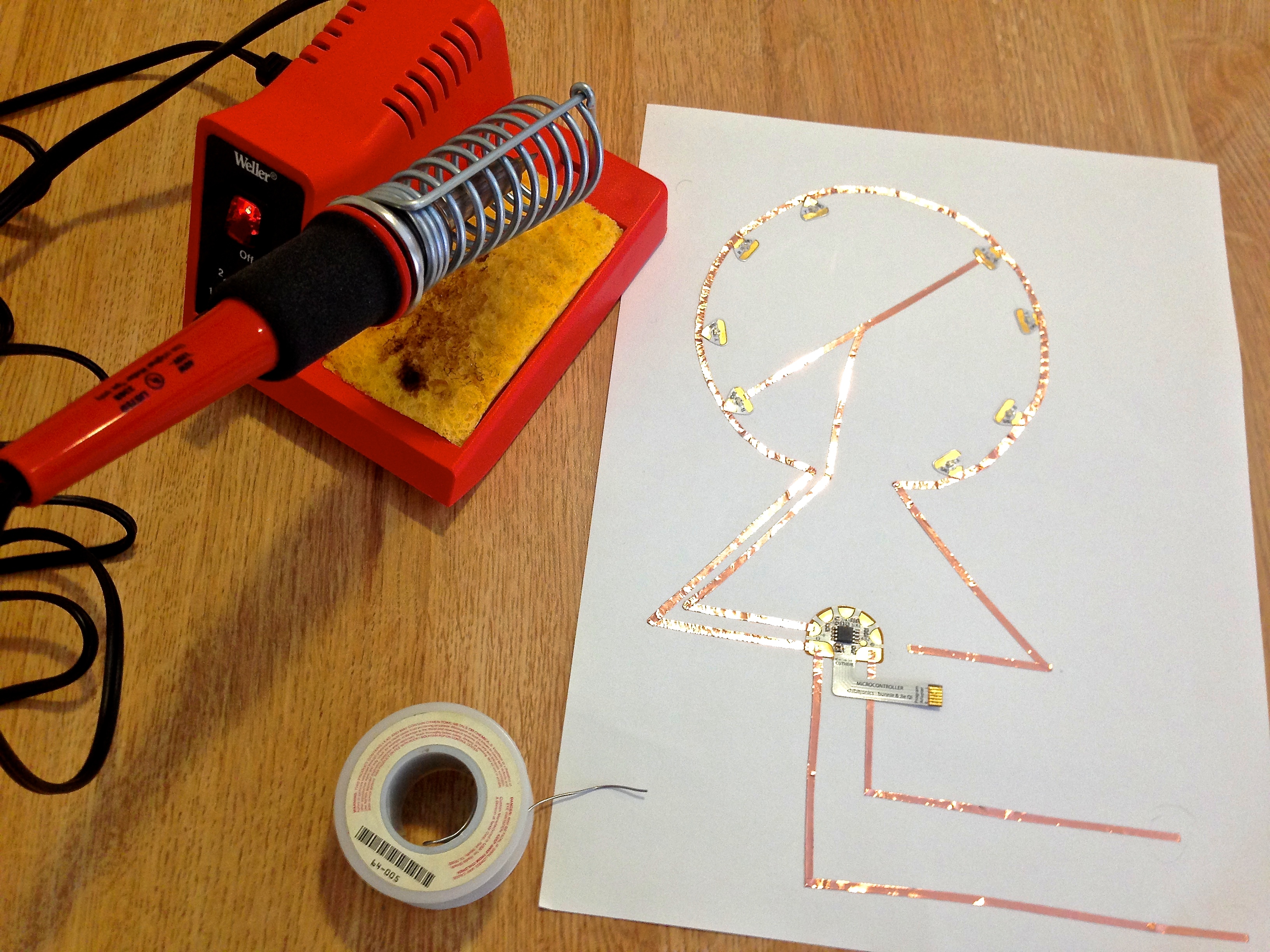
- Soldering Iron (not pictured)
- Solder
- Cardstock
- Colored Construction Paper
- Glue
- Scissors

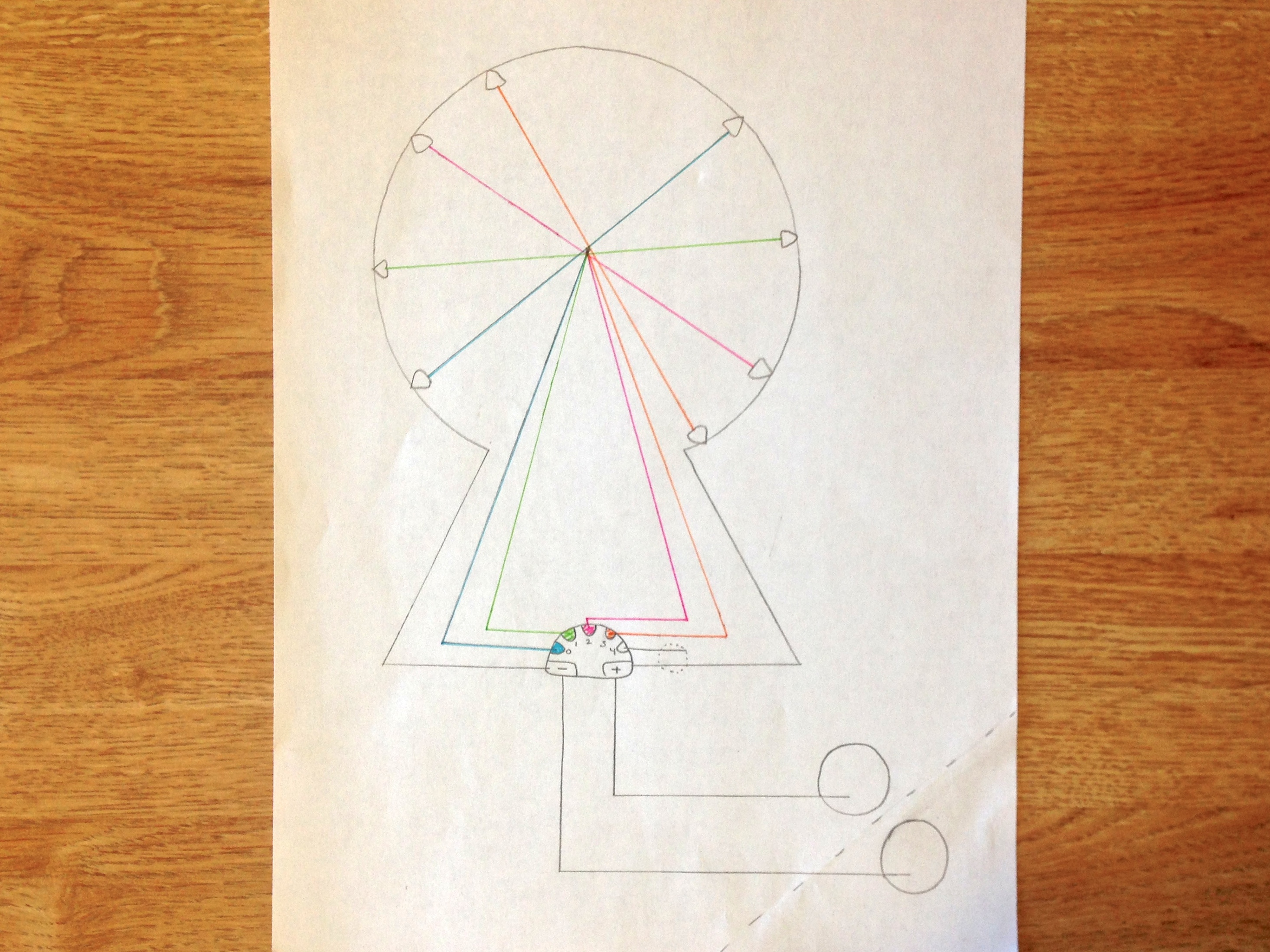
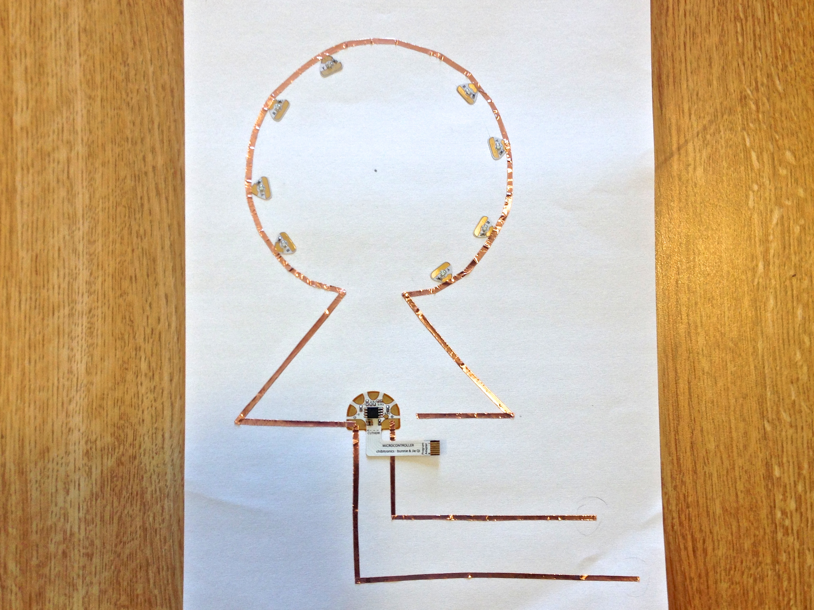
Preparation: On a piece of scrap paper, plan the circuit you want to create. Make sure every LED is connected to the negative strip of copper tape and one pin of the microcontroller.
NOTE: In my plan, I used different colors to indicate which pieces of tape would touch each pin. In the center of the wheel, there will be pieces of paper between each layer (each color) so the tape will not overlap.
Programming Instructions:
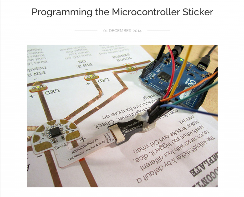
Step 1. See “Programming the Microcontroller Sticker” to learn how to set up your microcontroller and computer to begin coding.
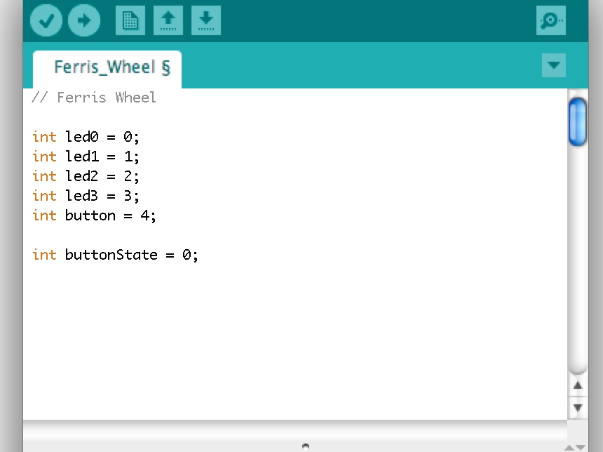
Step 2. Once you know which LEDs correspond to which pins on the microcontroller it is time to begin writing your code:
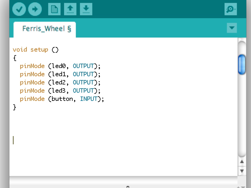
- Give each pin you will be using a name and set “buttonState” to zero.
- Initialize pins 0-3 as output and pin 4 (the button) as input.
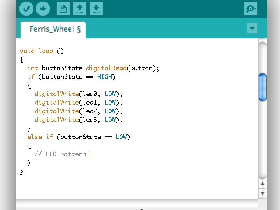
- Set up an “if” statement that will run the LED pattern if the button is pressed.
HINT: If your pin 4 is not connected to anything (which it should not be), then the “digitalRead” command randomly returns either HIGH or LOW. Whichever value it returns is changed once the button is pressed, allowing the “else” function of your “if” statement to be carried out.
- To reduce the lines of code needed in your program this tutorial shows how to create a basic function. When called, this function will cause your LEDs to light up in sequence around the circle of your ferris wheel. This will be you “circle” function. To create this function, first define the function by typing int circle ( ). Here, the empty parenthesis indicates there is no input required for your function.
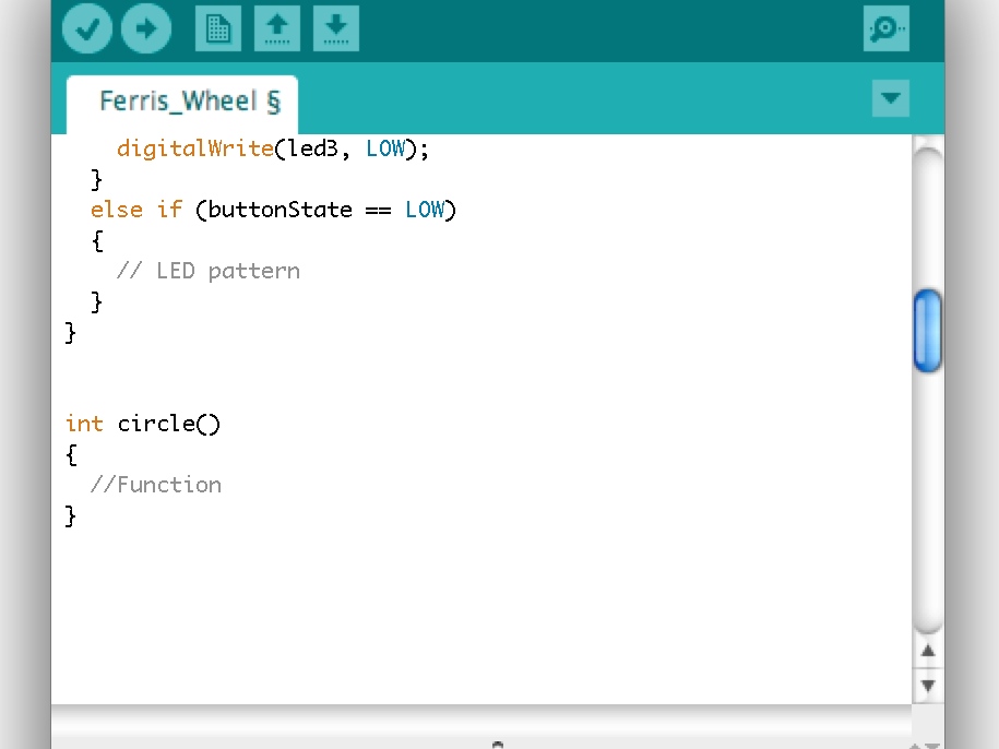
- Below this, within a set of brackets, write out the commands that the function will perform- turning the LEDs on and off in sequence.
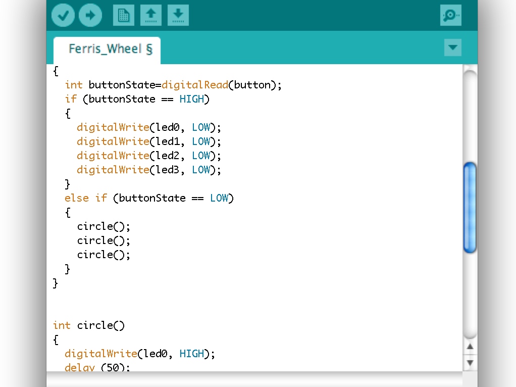
HINT: The command “digitalWrite(pin, value)” takes a pin and sends a voltage across it. If the value is “HIGH”, the voltage will be set to 5V and the LED will turn on. If the value is “LOW”, the voltage will be set to 0V (Ground) and the LED will turn off.
HINT: The command “delay” will delay the next command in the sequence by the input number of milliseconds.

- Call your circle function inside your else if statement by typing the name of the function followed by any inputs (in this case there are none). Call the function as many times as you want the LEDs to complete a full circle when pressed once.
- Upload code to the microcontroller
Notes:
– It may be helpful to attach your microcontroller to the Attiny85 Microcontroller Template while you program to ensure all your code is working correctly.
– This program could also be written without using a function, but the code would be much longer.
Crafting Your Circuit
In this technique, you will first place your LEDs, then connect them using copper tape. Because the tape will be placed on top of the LEDs’ conductive pads, rather than underneath, it will only form a weak connection. To fix this problem, you will then have to solder the copper tape to the LED.
Step 1. Based off your sketch, place your LEDs and your programmed microcontroller sticker on a piece of cardstock. It may help to draw a light reference circle on the cardstock so that your LEDs are properly spaced around the wheel.

Step 2. Begin adding copper tape to your circuit. Start by laying the outermost piece of tape (connected to the negative terminal of the microcontroller) and the two pieces connecting the microcontroller to the battery.
HINT: to make the tape thinner, cut it in half length wise.
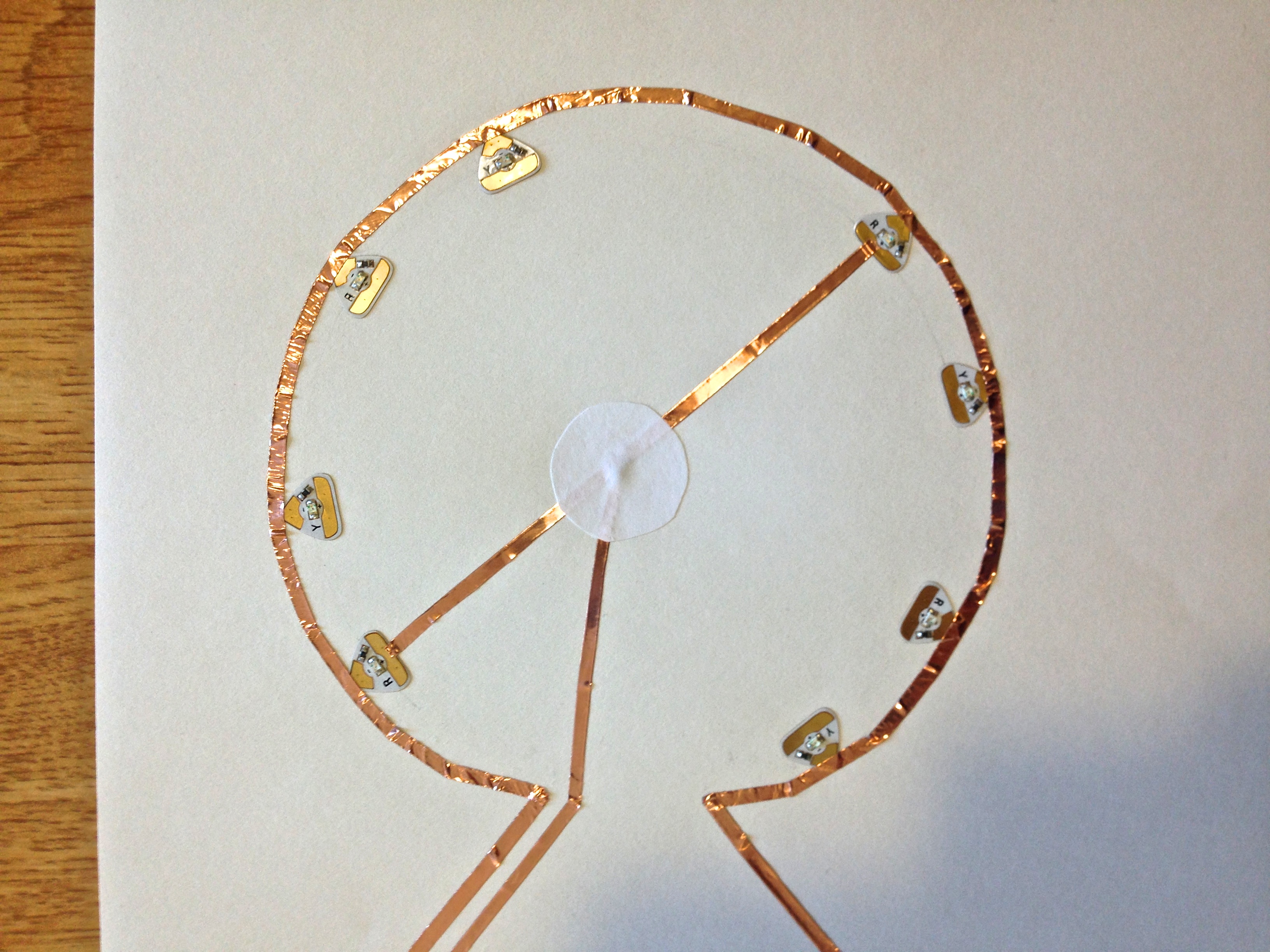
Step 3. Use copper tape to create the first spoke of the ferris wheel (drawn in blue on my sketch). Because the piece of copper tape attached to the microcontroller forks into 2, create the spoke out of a separate piece of tape. This will later be joined to the first piece by soldering.
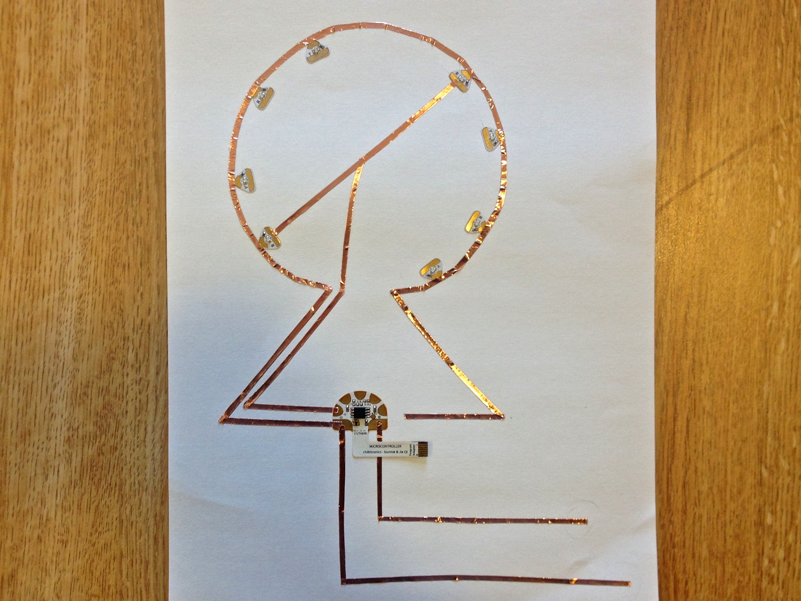
Step 4. Solder together the 2 pieces of copper tape of the fist spoke in the center of the ferris wheel. Click here for brief tutorial on how to solder.
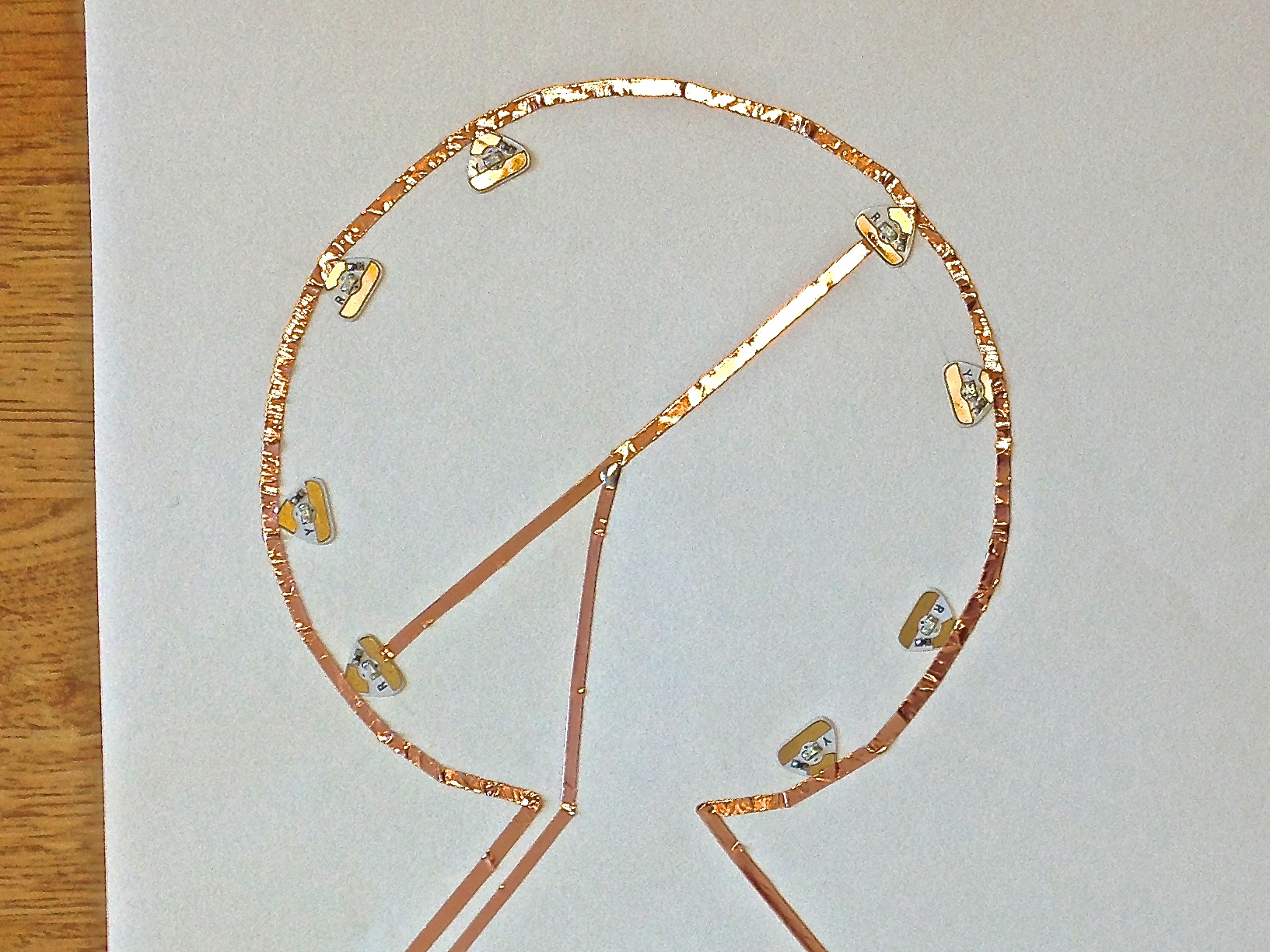
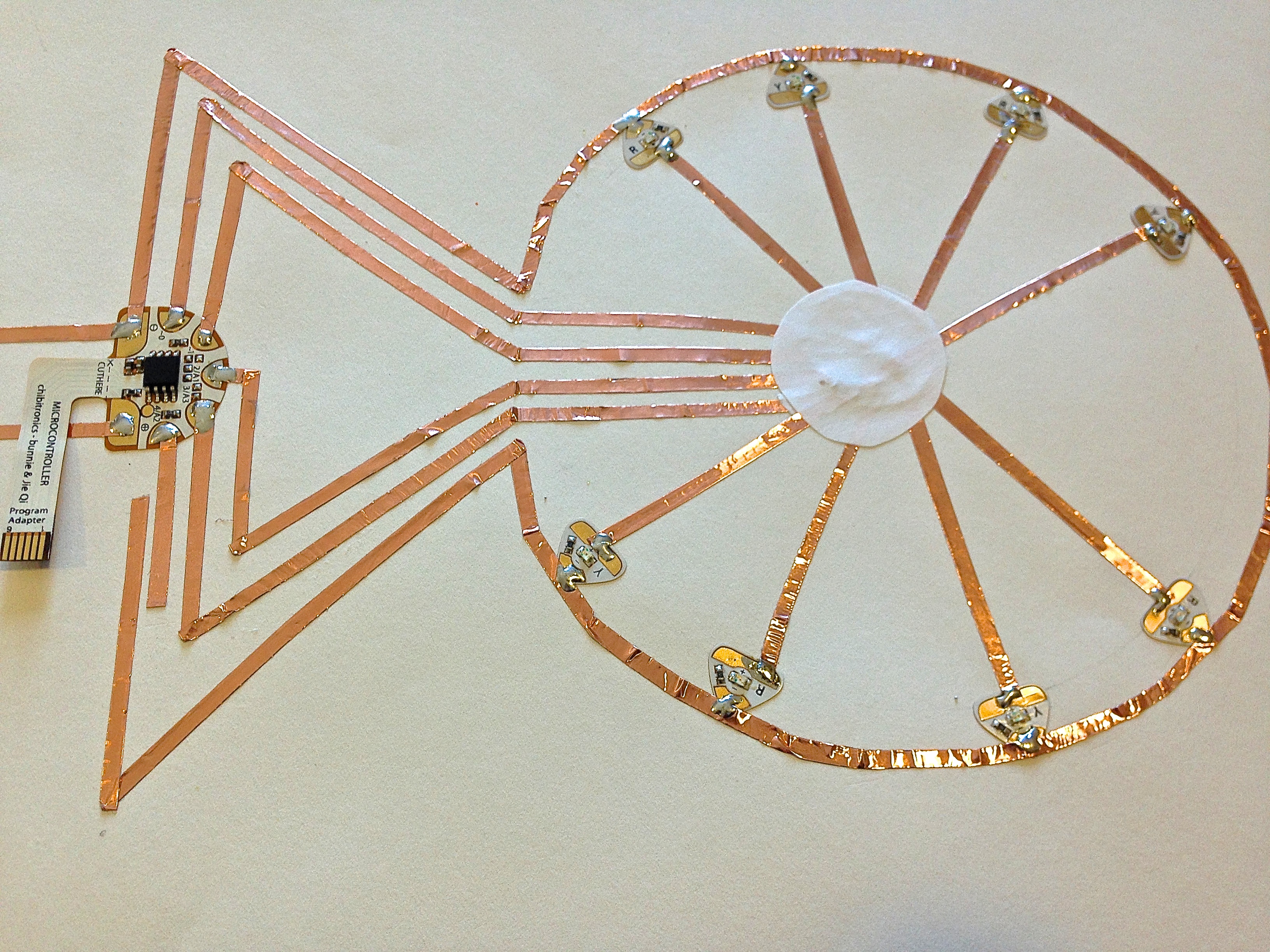
Step 5. Cut out a small circle of paper. Glue this over the center of your ferris wheel to prevent the copper tape of the first spoke from touching your second spoke.
Step 6. Lay copper tape for the second spoke of the ferris wheel. Once again, solder the connection in the center of the wheel, then glue a piece of paper over the connection. Repeat for spokes 3 and 4.
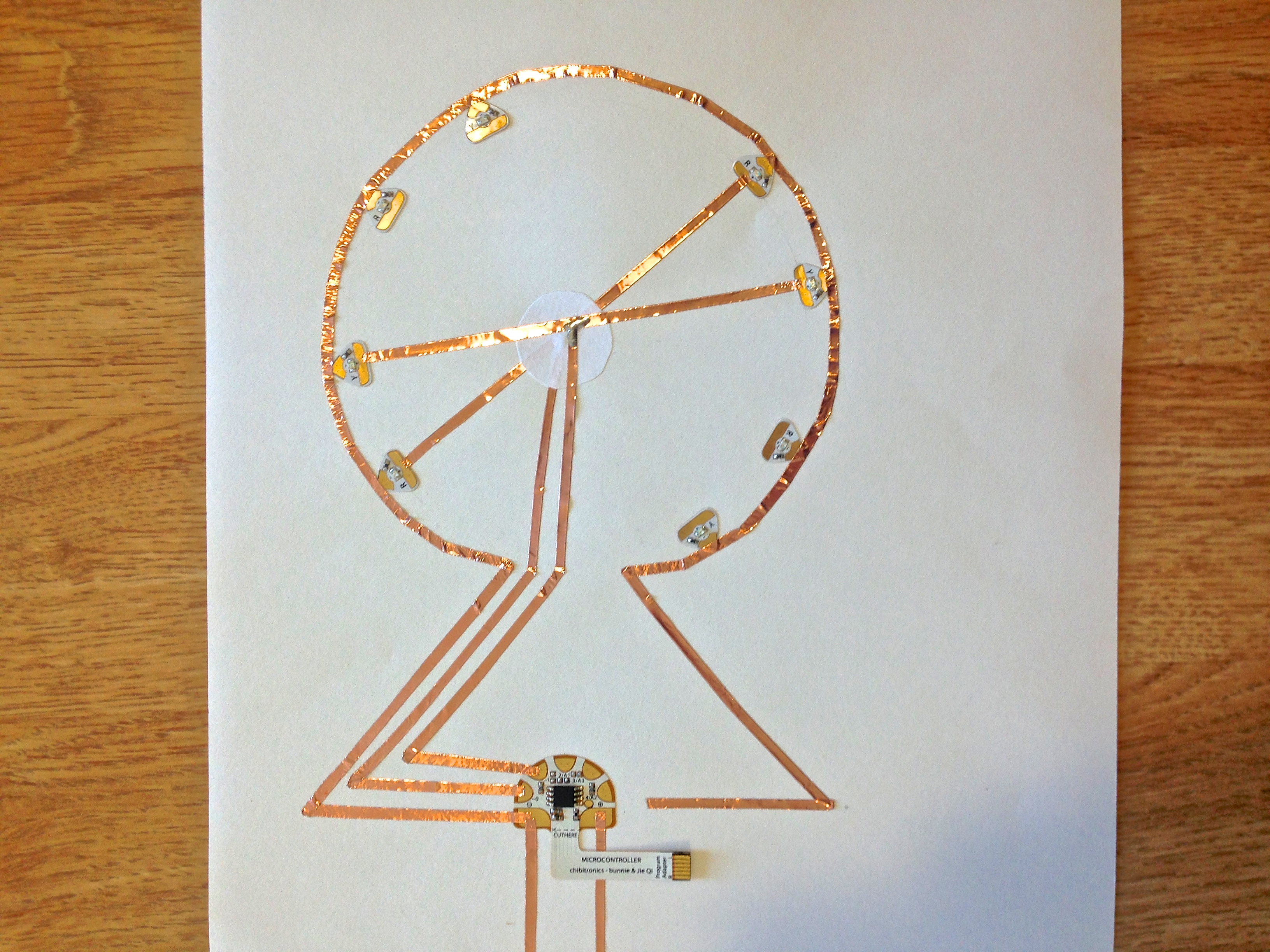
Step 7. Add a piece of copper tape to pin 4 of the microcontroller to create your button.
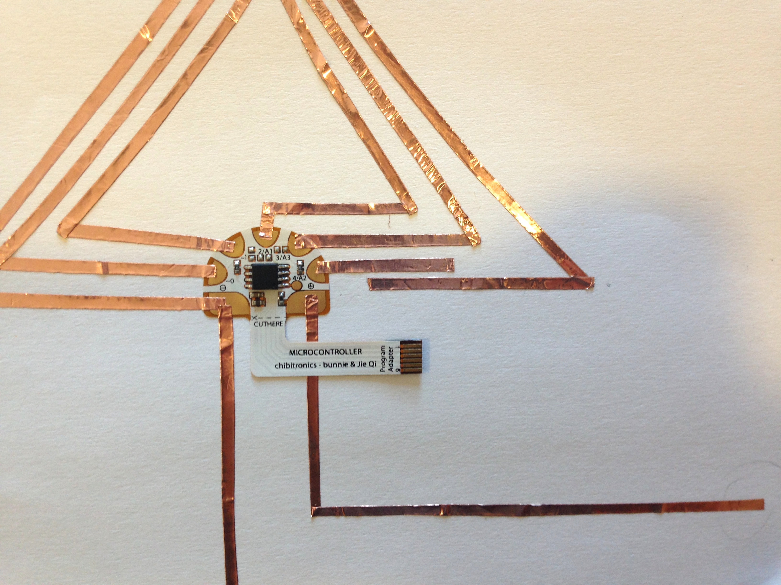
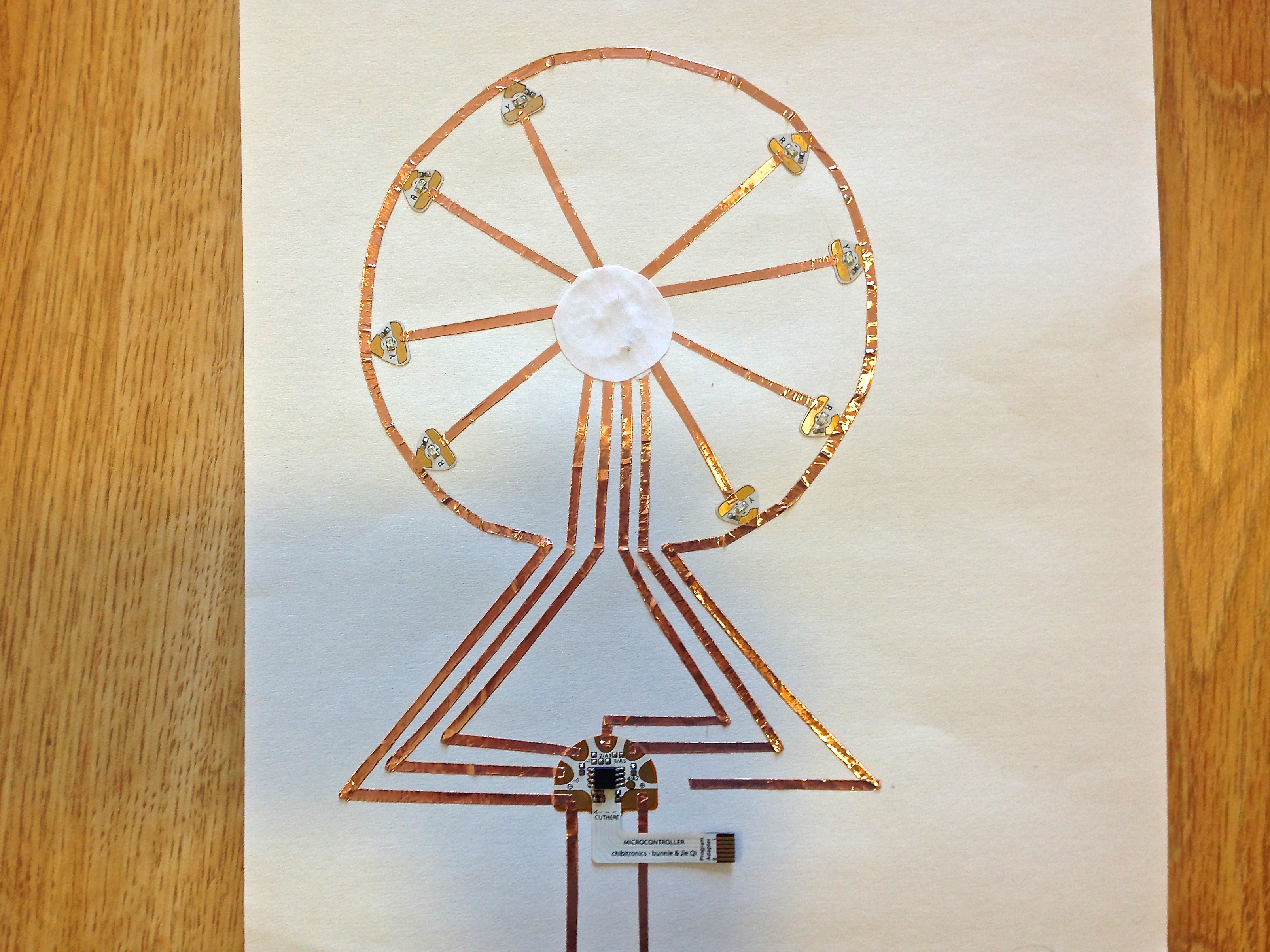
Step 8. Solder all the remaining connections between the copper tape and the conductive pads of the circuit stickers.
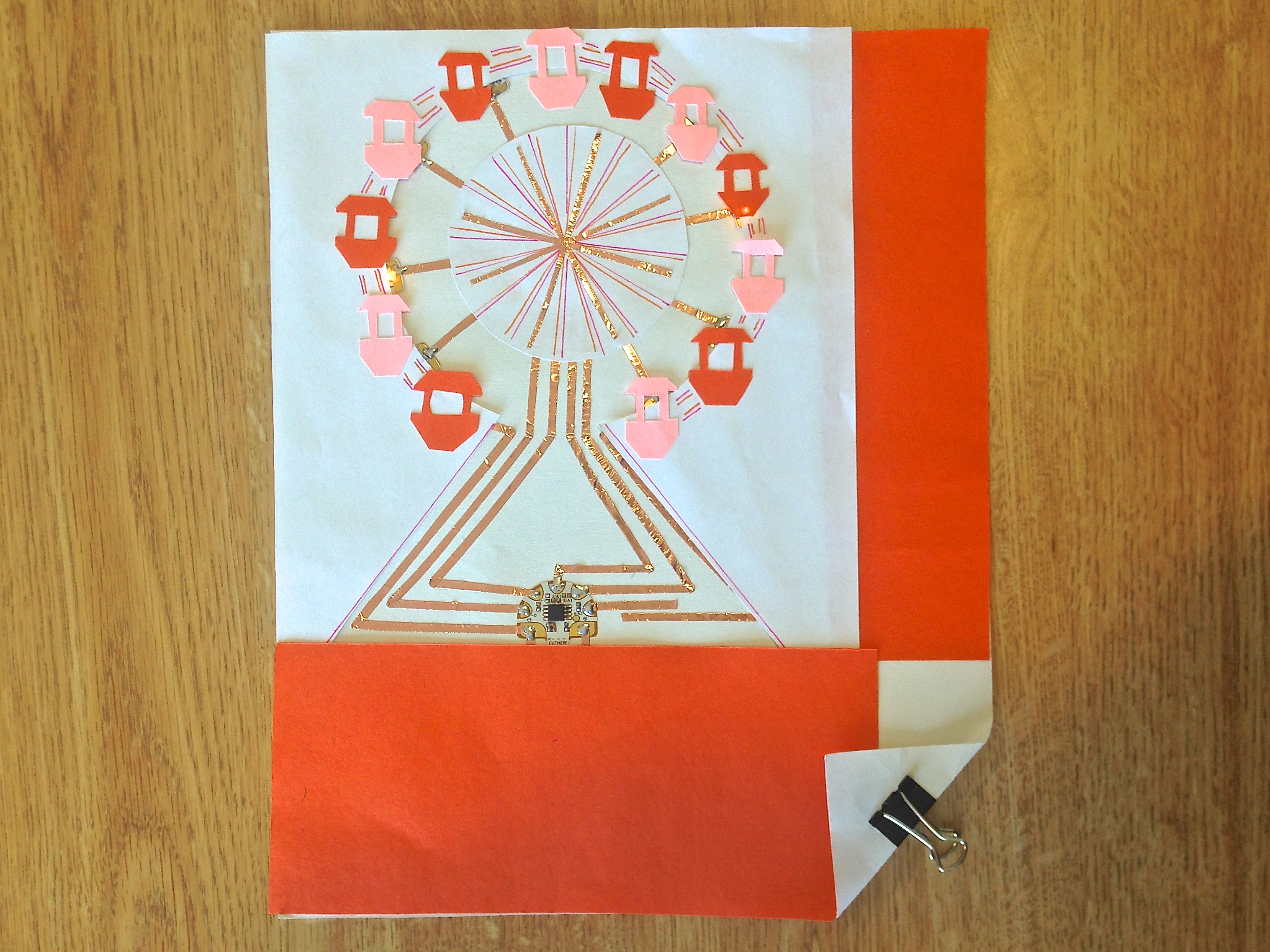
Step 9. Decorate with construction paper and add a battery to complete your ferris wheel!