The microcontroller circuit sticker comes with a default touch sensor program. However, you can also use Arduino software to reprogram it with your own code! This tutorial will show you how to reprogram the Attiny85 microcontroller sticker using three programmer options: the Tiny AVR programmer, the AVRISP MKII, and the Arduino as programmer .
 |
 |
 |
| Tiny AVR Programmer | AVRISP MKII | Arduino |
MATERIALS AND TOOLS
-
- An In System Programmer (ISP) to connect the microcontroller sticker to the computer and load your code, such as:
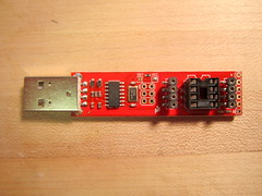
- Tiny AVR programmer this programmer is easiest to start with. It also has a convenient connector for easily programming bare Attiny85 microcontrollers
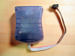
- AVRISP MKII this can be used to program any sort of AVR microcontroller
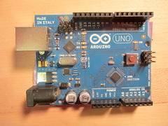
- Arduino as programmer If you have an Arduino handy, you can also use it as a programmer. To do so, you will first need to program your Arduino board as a programmer. Here are tutorials for turning the Arduino UNO and Arduino Leonardo into ISPs. For the Arduino UNO, you will also need a 10uF or larger capacitor.
- microcontroller circuit sticker (in the Sensors add-on)
- circuit sticker programming adapter (also included in the Sensors add-on)
- 5 LED stickers
- 6 jumper wires
- copper foil tape
- non-conductive tape, such as scotch tape, duct tape or masking tape
- Download:
- For Arduino 1.6 (recommended): ide-1.6.x.zip (hosted by David Mellis at GitHub)
- For Arduino 1.0: ide-1.0.x.zip (hosted by David Mellis at GitHub)
- An In System Programmer (ISP) to connect the microcontroller sticker to the computer and load your code, such as:
- Download: chibi_micro_v1p1.ino (hosted by bunnie at GitHub). This is the default touch sensor Arduino code preprogrammed onto the microcontroller stickers
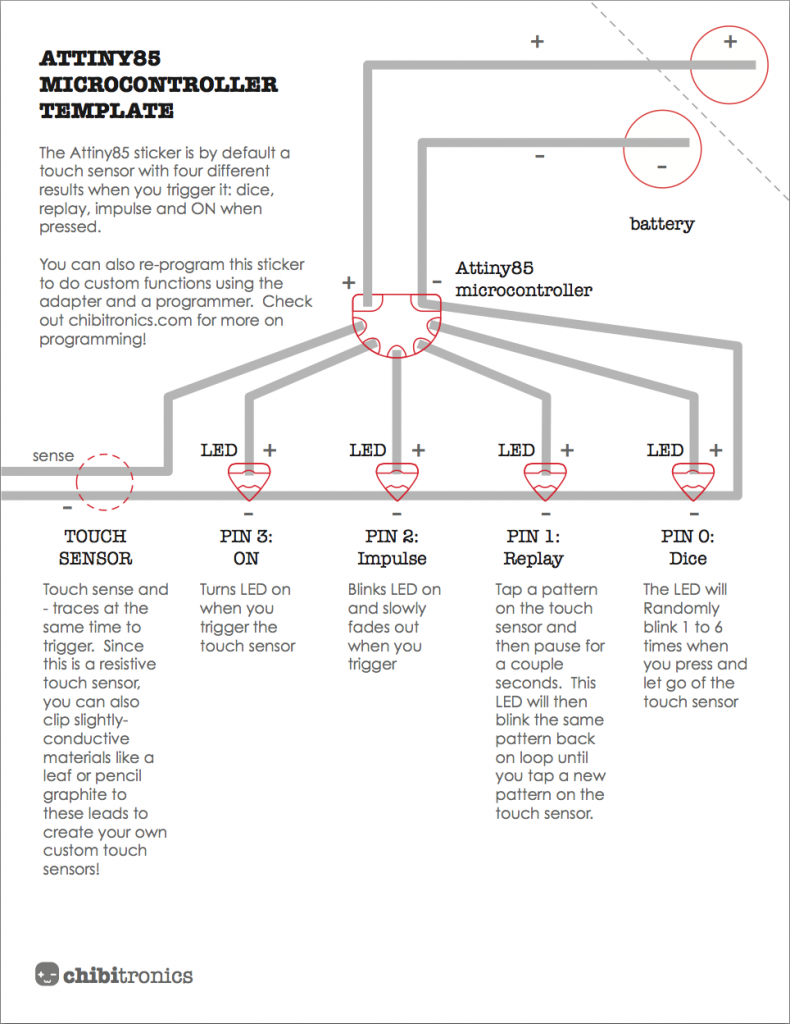
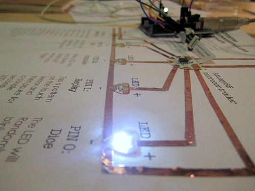
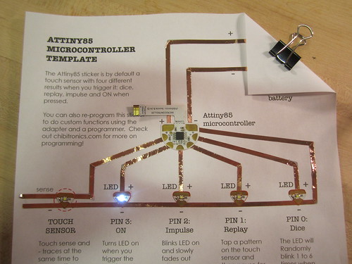
STEP 0: BUILD TEST CIRCUIT
Before programming the microcontroller, first create a test circuit for the microcontroller sticker using the Attiny85 microcontroller template and LED stickers. There is a full tutorial here.
STEP 1: DOWNLOAD AND INSTALL ARDUINO
Download Arduino onto your computer and follow the installation instructions for Mac OS X or Windows.
STEP 2: DOWNLOAD AND INSTALL ATTINY SUPPORT FOR ARDUINO
Download attiny-master.zip support files for Arduino. To install:
- Find your Arduino Sketchbook folder and create a new subfolder called “hardware,” if one doesn’t exist already. If you have trouble finding your Sketchbook folder, look under File > preferences.
- Unzip the attiny-master.zip file and inside should be a folder called “attiny-master” and inside that should be another folder called “attiny.”
- Copy the “attiny” folder into the “hardware” folder, so that you have the structure Documents > Arduino > hardware > attiny. Inside the attiny folder should be the file boards.txt and another folder called variants. Inside the hardware folder
- Restart Arduino. Now under Tools > Board menu you should see entries for ATtinys.
For a more detailed tutorial on Attiny support installation, check out “Programming in Arduino” section of Sparkfun’s Attiny Programmer Hook Up Guide.
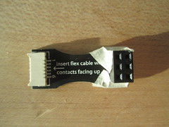
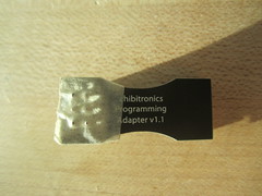
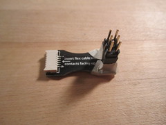
STEP 3: TAPE YOUR PROGRAMMING ADAPTER
To prevent potential short circuits, put a bit of non-conductive tape on the bottom of your circuit sticker programming adapter.
 |
 |
STEP 4: CONNECT YOUR PROGRAMMER TO THE ADAPTER
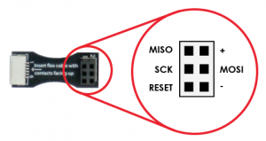
You will need to connect your programmer to the Circuit Sticker programming adapter, which will then connect to the programming tail of the microcontroller sticker. The pinout of the adapter is:
This step depends on which programmer you use:
- AVRISP MKII
Keep the 6-pin header that comes with the circuit sticker programming adapter and simply plug the AVRISP MKII onto these pins as shown below:
- Tiny AVR Programmer
Use your jumper wires to connect the adapter to the Tiny AVR Programmer as shown below:
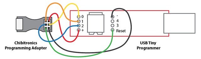
The connections you need to make are: - red: + to +
- yellow: MOSI to 0
- black: – to –
- orange: MISO to 1
- blue: SCK to 2
- green: RESET to reset
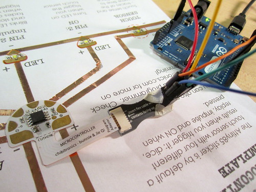
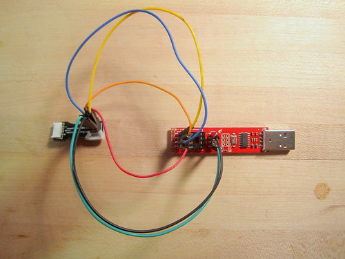
- Arduino as ISP
Use your jumper wires to connect the adapter to the Arduino as shown below:
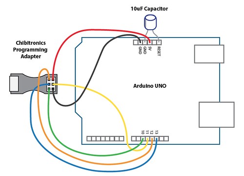
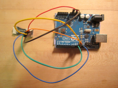
The connections you need to make are: - red: + to 5V
- yellow: MOSI to pin 11
- black: – to GND
- orange: MISO to pin 12
- blue: SCK to pin 13
- green: RESET to pin 10
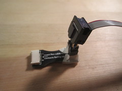
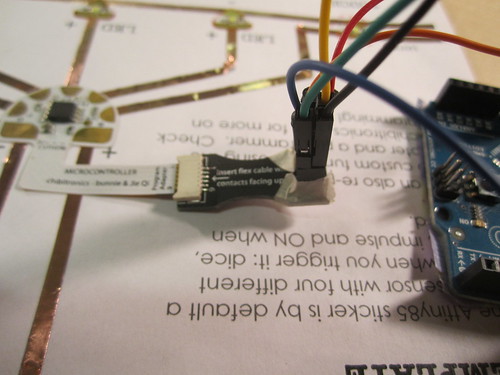
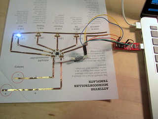
STEP 5: CONNECT ADAPTER TO MICROCONTROLLER STICKER
Now you are ready to connect the microcontroller sticker to the programmer!
If you are using the Tiny AVR Programmer or the Arduino ISP, make sure to take the battery out of the test circuit first. Then, simply insert the programming tail into your adapter and plug your programmer into your computer:
 |
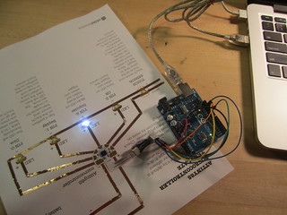 |
If everything is connected properly, the microcontroller should power on and run the default program. The lights will appear brighter because the circuit is now being powered by your 5V computer USB port instead of the 3V coin cell battery.
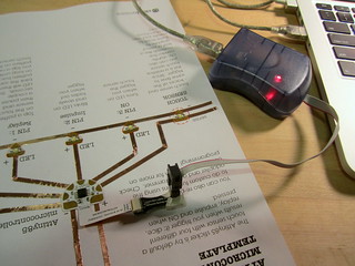
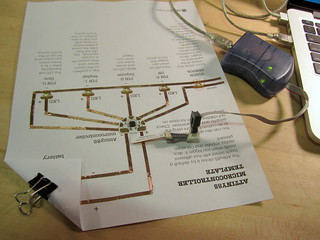
If you are using the AVRISP MKII, insert the programmer tail into adapter and plug your programmer into the USB port of your computer. Since this programmer does not provide power to the microcontroller, you will also need to add a fresh coin cell battery to your test circuit. Without battery power, the AVRISP will shine a red light (left). Once you put in a fresh battery, the light should turn green (right).
 |
 |
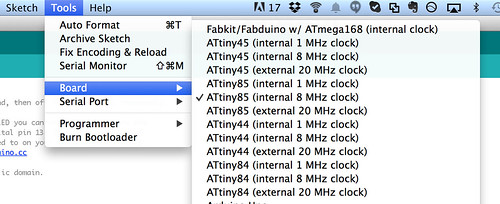
STEP 6: CONFIGURE ARDUINO FOR ATTINY85 AND PROGRAMMER
Next you will need to choose the correct settings in Arduino for the Attiny85 and your programmer:
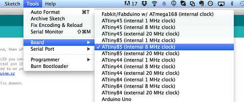
- Select Tools > Board > ATtiny85 (internal 8MHz clock)
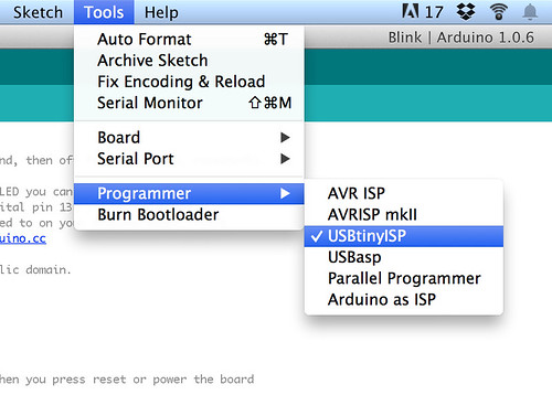
- Under Tools > programmer, select the programmer you are using. In this example, we are using the Tiny AVR programmer, which is the USBTinyISP
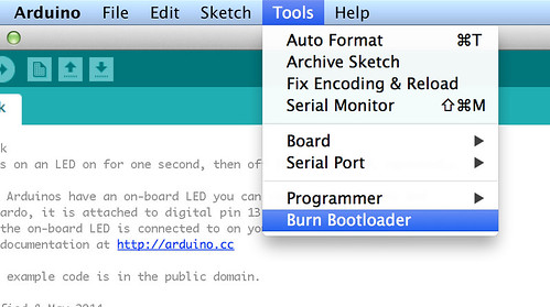
- Select Tools > Burn Bootloader to burn the bootloader and test that all of your connections were made properly.
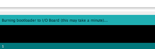
If everything is connected properly and the bootloader is successfully loaded, you will see the following messages on the lower left:
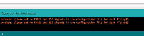
If you see an error message, check to make sure that the connections between the computer, programmer, adapter and microcontroller sticker are correct. Often a simple loose connection will result in programming errors!
Once the bootloader is successfully burned, the microcontroller is now “blank,” meaning it has no program on it. As a result, it will no longer be running the default program and will not respond to touch anymore. If you would like to reprogram the microcontroller sticker with the default touch sensor program, you can find the code here (hosted on GitHub).
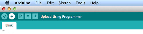
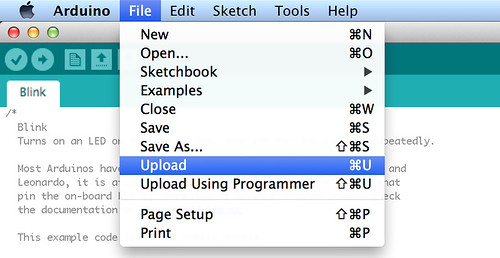
STEP 7: UPLOAD YOUR PROGRAM!
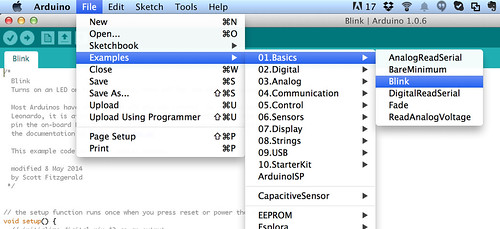
Now you’re ready to upload your own code! To get started, let’s try making changes to some existing code:
- Open the Blink example Sketch under File > Examples > 01. Basics > Blink
- In the code, replace “13” with “0”. This code will then blink lights attached to pin 0 of the microcontroller sticker.
- Upload the code by clicking the (->) upload icon or go to File > Upload
- Done! You should now see the LED on pin 0 (originally, the Dice LED) blink on and off.
Now try unplugging the microcontroller sticker from the adapter and adding a battery. The program will continue to run because the code is now saved on the microcontroller.
TRY THIS: LEDS BLINKING IN SEQUENCE
Here is some code that will make the LEDs blink in sequence:
/*

Blink Sequence

Turns on the LED on for one second, then off for one second, in sequence from Pin 0 to Pin 4
*/
// Give the pins a name
int led0 = 0;
int led1 = 1;
int led2 = 2;
int led3 = 3;
int led4 = 4;
// the setup routine runs once when you press reset:
void setup() {
// initialize the digital pins as outputs.
pinMode(led0, OUTPUT);
pinMode(led1, OUTPUT);
pinMode(led2, OUTPUT);
pinMode(led3, OUTPUT);
pinMode(led4, OUTPUT);
}
// the loop routine runs over and over again forever:
void loop() {
digitalWrite(led0, HIGH); // turn the LED on (HIGH is the voltage level)
delay(1000); // wait for a second
digitalWrite(led0, LOW); // turn the LED off by making the voltage LOW
delay(1000); // wait for a second
digitalWrite(led1, HIGH); // turn the LED on (HIGH is the voltage level)
delay(1000); // wait for a second
digitalWrite(led1, LOW); // turn the LED off by making the voltage LOW
delay(1000); // wait for a second
digitalWrite(led2, HIGH); // turn the LED on (HIGH is the voltage level)
delay(1000); // wait for a second
digitalWrite(led2, LOW); // turn the LED off by making the voltage LOW
delay(1000); // wait for a second
digitalWrite(led3, HIGH); // turn the LED on (HIGH is the voltage level)
delay(1000); // wait for a second
digitalWrite(led3, LOW); // turn the LED off by making the voltage LOW
delay(1000); // wait for a second
digitalWrite(led4, HIGH); // turn the LED on (HIGH is the voltage level)
delay(1000); // wait for a second
digitalWrite(led4, LOW); // turn the LED off by making the voltage LOW
delay(1000); // wait for a second
}
Copy and paste this code into the Arduino window and upload directly. Try playing with the delay times to create different blink rhythms! You will need to modify your test circuit by adding one more LED on Pin 4, where the touch sensor used to be, like this:
WRITE YOUR OWN CODE!
The following Arduino commands should be supported:
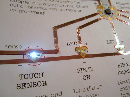
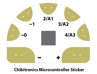
These are the pinouts for the microcontroller sticker and Attiny85:
 |
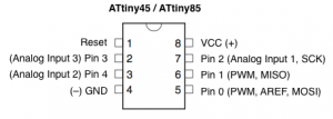 |
Note: there is a 4 megaOhm resistor between Pin 4 and + on the microcontroller to create a resistive touch sensor.
For additional sample code, check out the examples at the bottom of this page
Happy coding!
REFERENCES
-
- Programming an ATtiny with Arduino Tutorial by David Mellis
- Arduino Board as ATtiny Programmer Tutorial by David Mellis
- Tiny AVR Programmer Hookup Guide from Sparkfun