How To > Batteries and Power > Tutorial
USB Powered Paper Circuits:
An Alternative to Coin Batteries
Written by: Jill Dawson
Plug It In!
Coin batteries are great for powering paper circuits, but they can be costly — both in terms of expense and environmental impact.
In this tutorial, designed for people with advanced electronics skills, we will show you how to safely substitute USB power for coin batteries, to help you power your circuits more sustainably.
But, before you jump in, please be sure that you read and understand all of the safety tips we’ve outlined.
While nothing bad can happen to you or your paper circuits if you accidentally flip a coin battery the wrong way, plugging a paper circuit into a computer or wall socket comes with additional risks. Mixing up the polarity, or shorting out your circuit, can lead to overheating, damage to your project or PC, and even electrical fires.
Always remember: Safety First!
Power Your Project with USB!
Related
- Paper Circuits STEAM Educators Guide (See Featured Projects)
- Testing Continuity With a Multimeter
- Haunted House
Categories
Safety First
While powering a paper circuit with USB power is a sustainable alternative to coin batteries, we only recommend it for advanced electronics users!
Children should not attempt to connect their paper circuits to USB power without adult permission, assistance, and supervision.
When using USB power, it’s essential to protect your LEDs with resistors, or they will burn out.
- Note: Circuit Sticker LEDs have built in resistors to eliminate the guesswork. If you are using through hole LEDs, a resistor of roughly 150 ohms should protect your LEDs. But it is better to choose specific resistor values based on the LED color as different colors require slightly different resistances.
Please proceed at your own risk.
Introduction
Small, discreet coin batteries are fairly accessible and easy to use. However, relying upon them exclusively for powering paper circuit projects comes with trade-offs. They don’t last very long, for example, if they are used to power a circuit containing several LEDs. And while they may be easily removed or switched off to conserve battery life, they are not ideal for projects designed to be left turned on for long stretches of time, collaborative projects that combine many small circuits into a larger display, or for powering microcontroller programmed circuits which require more electricity to run.
While coin batteries are convenient, they can also be costly — both in terms of the expense required to replace them and their potential impacts upon the environment. Replacing coin batteries with a more sustainable method such as USB power, one that generates a consistent power source without generating eco-waste, is easier than you might imagine!
Here are a few of the pros and cons to consider before deciding whether you want to try using USB power in place of coin batteries in your paper circuit projects.
Pros & Cons of Using USB Power
Pros
- Using USB power is more sustainable than using coin batteries = less eco-waste.
- USB power is stronger than a coin battery (5V vs 3V and more current available). As a result, a USB powered circuit will have brighter LEDs.
- USB power is strong enough to power many devices that a coin cell battery cannot, such as motors and larger microcontroller circuits (such as a Chibi Chip).
- USB power is enough to power a collaborative project composed of many separate circuits.
- Multiple projects can be powered via a single USB hub.
- You can plug your circuit into any USB port, charging bank, or electrical outlet (using an adapter) for a reliable 5V energy source.
- Making your own USB to alligator clip cable enables you to repurpose outdated hardware.
Cons
- USB power requires access to a wall outlet, computer port, or charging bank.
- Using USB power is less portable than coin batteries and are generally tethered to the power source via cable. Even portable charging banks are heavier and bulkier than small coin batteries
- USB powered circuits require resistors to prevent LEDs from burning out.
- Safety can be an issue: higher power means greater risk of damaging your circuits if anything goes wrong. Therefore it is recommended only for those who are experience and comfortable working with more advanced circuits.
- Making your own USB to alligator clip cable requires soldering skills & specialized tools.
In summary, USB power is a great substitute for coin batteries if you need more power and don’t want to keep switching out batteries. However, because USB power is strong enough to do damage, only use it if you are comfortable working with circuits!
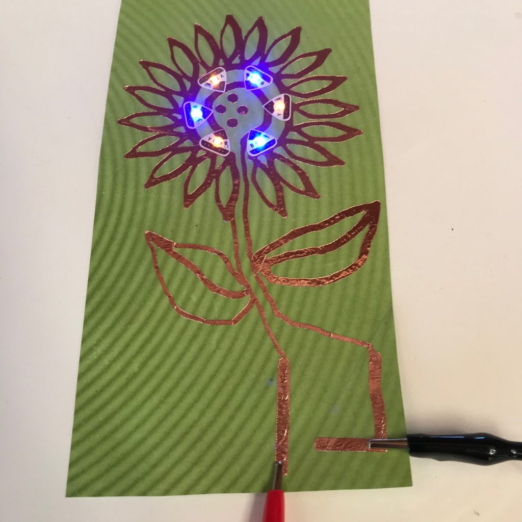
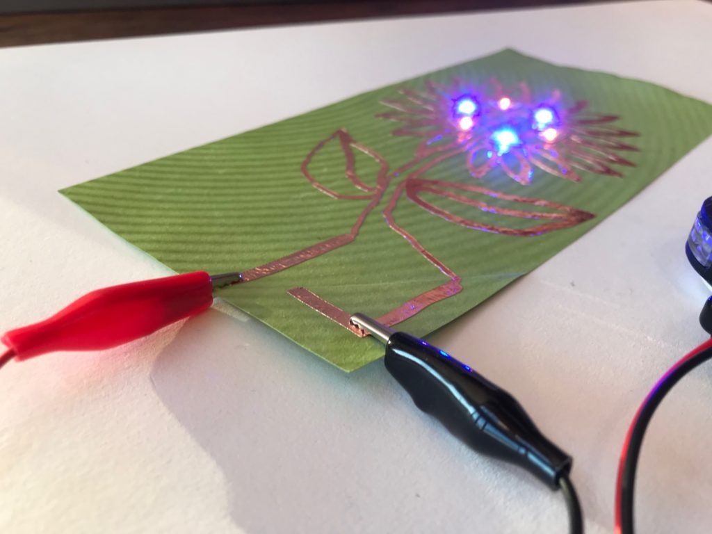
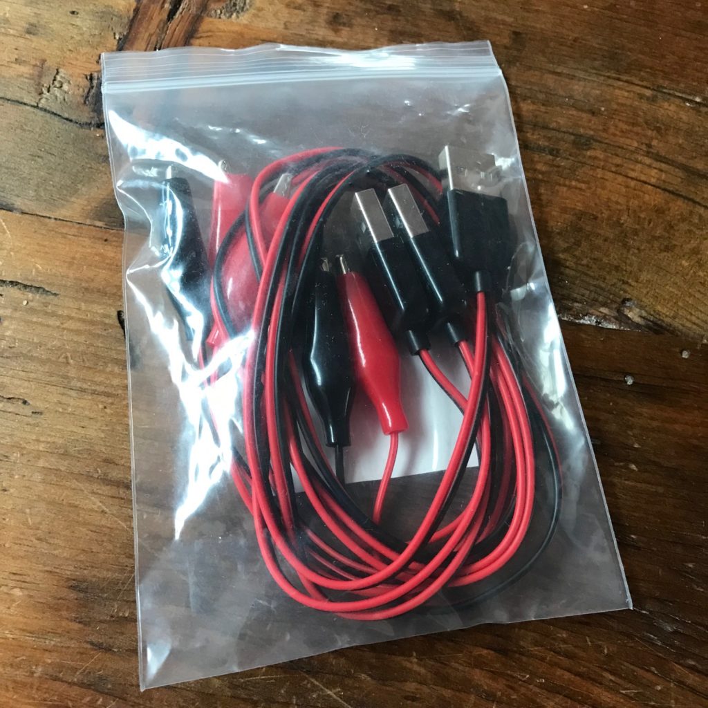
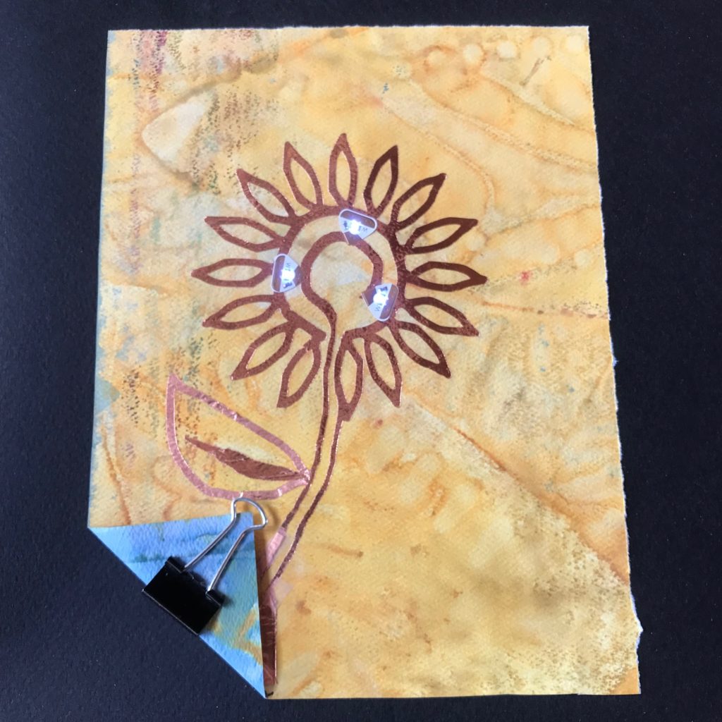
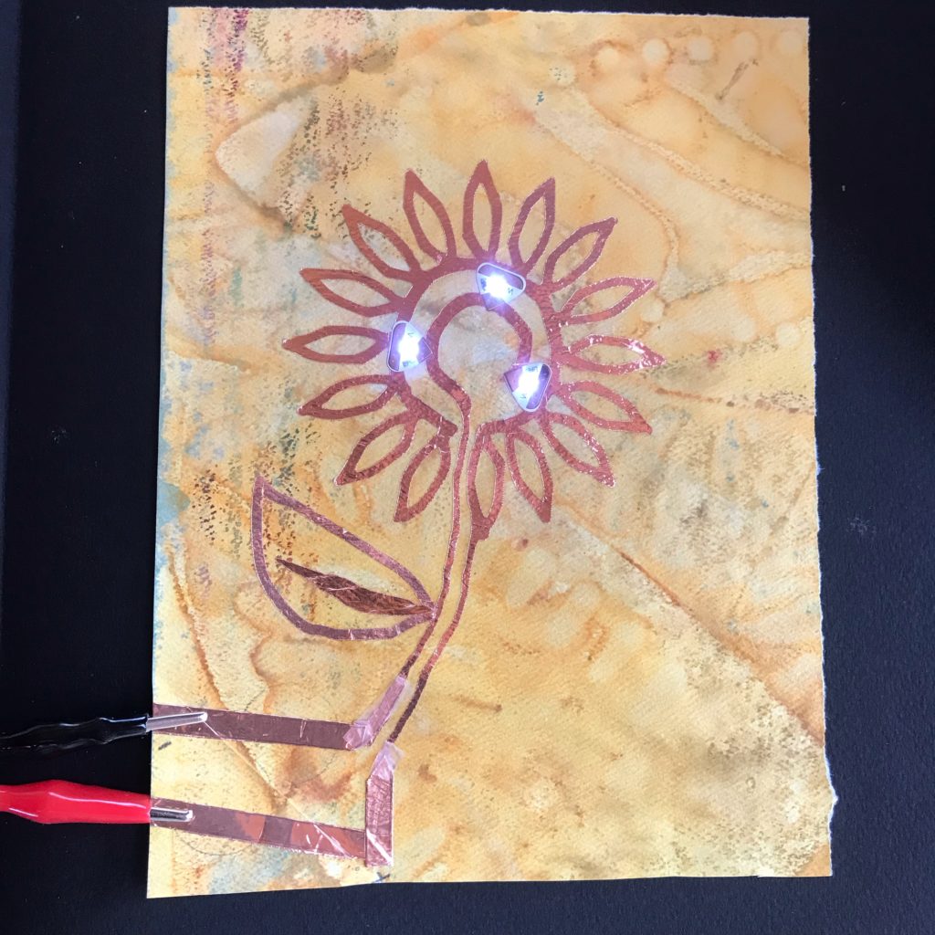
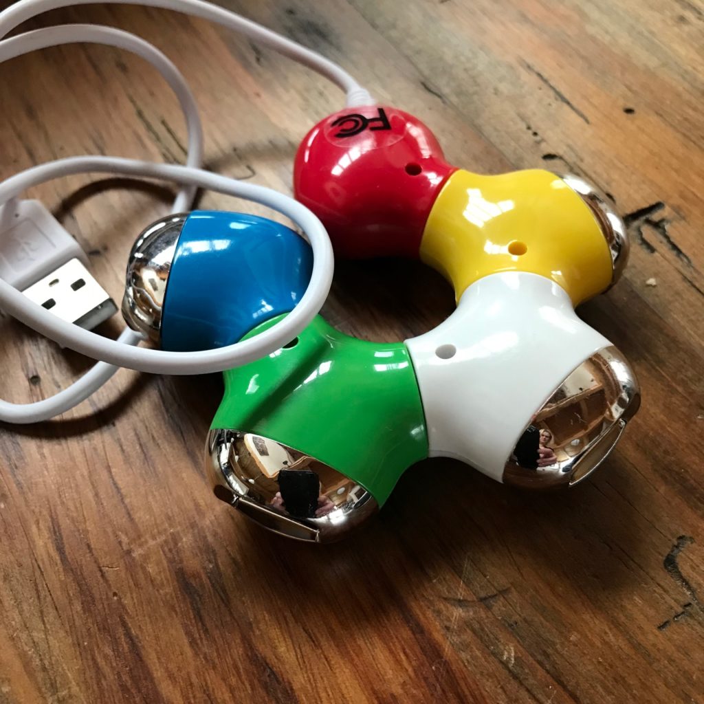
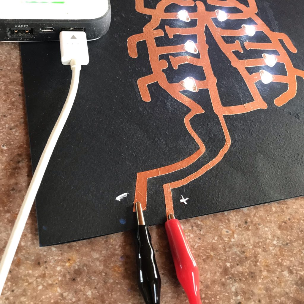
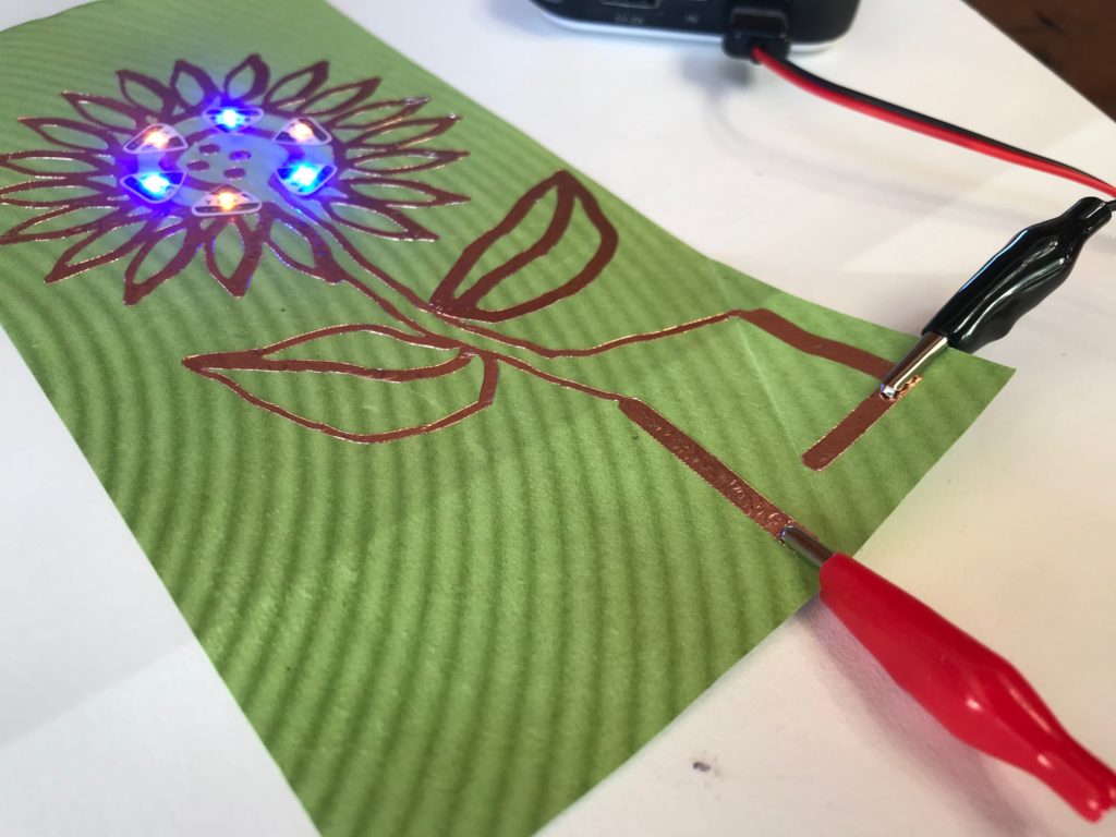
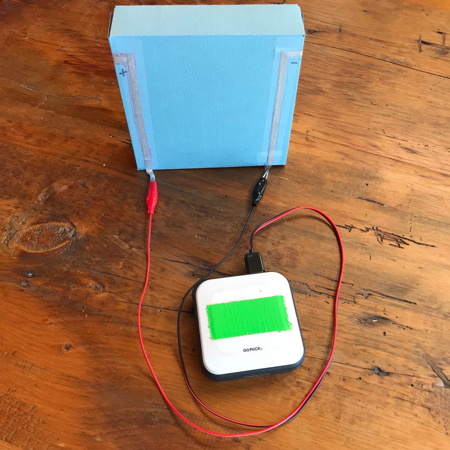
The easiest way to add USB to your paper circuit projects is by purchasing a pre-fabricated USB to alligator clip cable from an online vendor.
The alligator clips are useful, because they may be attached to the positive and negative leads of paper circuit projects — as a substitute for a coin battery. An advantage of using USB power is that the additional voltage will make your LEDs appear brighter than a coin battery.
As an alternative to a ready-made USB to alligator clip cable, you may make your own by following the directions in an upcoming section. But first, we’d like you to know a few USB basics.
Basics of USB
Universal Serial Bus (USB) compatible plugs and ports were developed to ensure a standardized method for safely powering a range of devices at a consistent 5V. Since USB powered devices can plug into a variety of ports to receive a reliable, low voltage source of energy, they are extremely versatile!
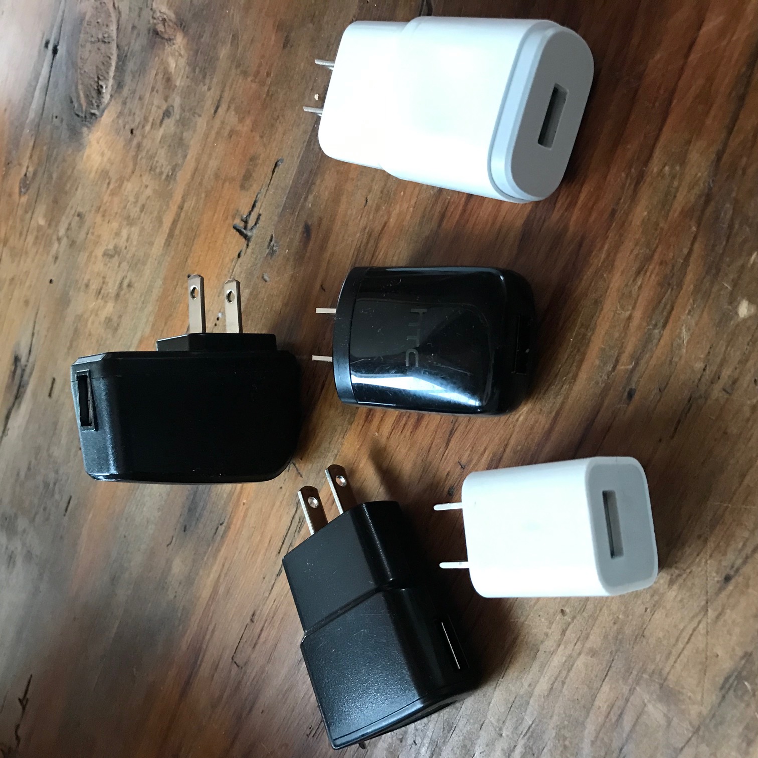
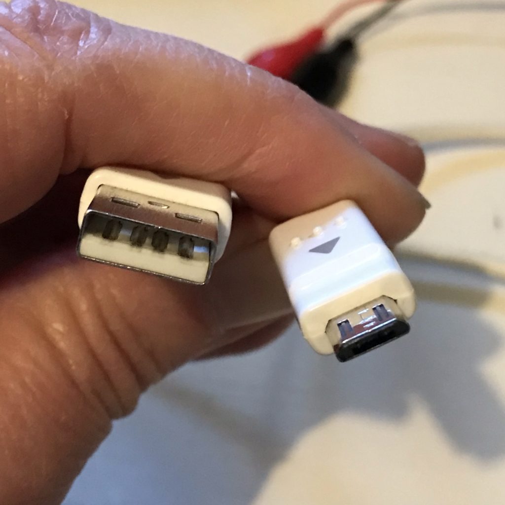
USB plugs may be found on the ends of cables and connected to small electronic devices such as keyboards or mice. Coming in different shapes and sizes, they are commonly found on smartphone charger cables, which typically have two differently shaped protrusions on each end: one that connects to a wall adapter or computer port, and another that connects to the device requiring power.
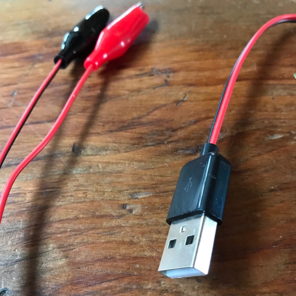
Many smartphone chargers and small devices such as tablets, electronic readers, and digital cameras may have a mini- or micro-USB plug on one end and a larger Type-A or Type-B USB plug on the other. The Type-A USB plug, which is rectangular, is the plug most useful for paper circuits; it is also known as a “Standard A” connector.
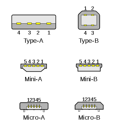
Image Courtesy of Bruno Duyé
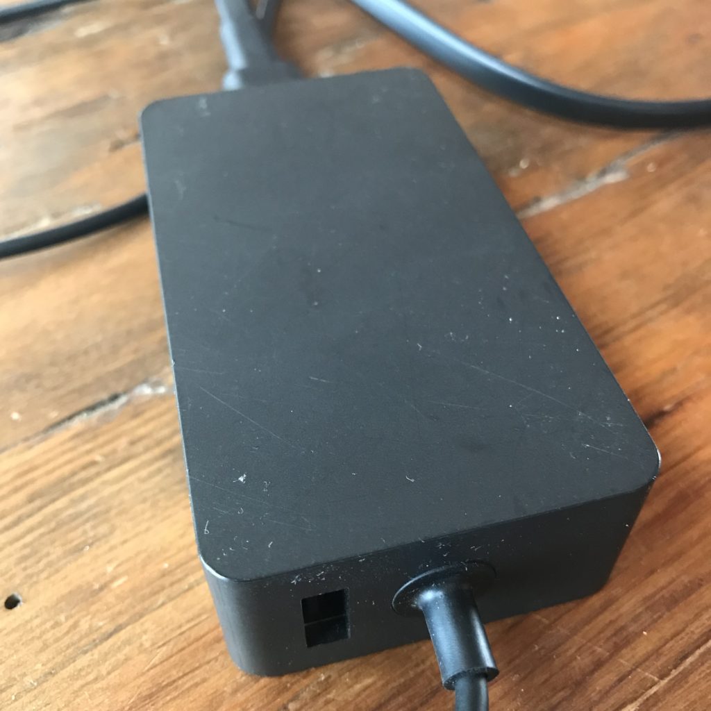
USB plugs are inserted into USB ports, which are rectangular openings that may be found on personal computers, power banks, chargers, and wall adapters.
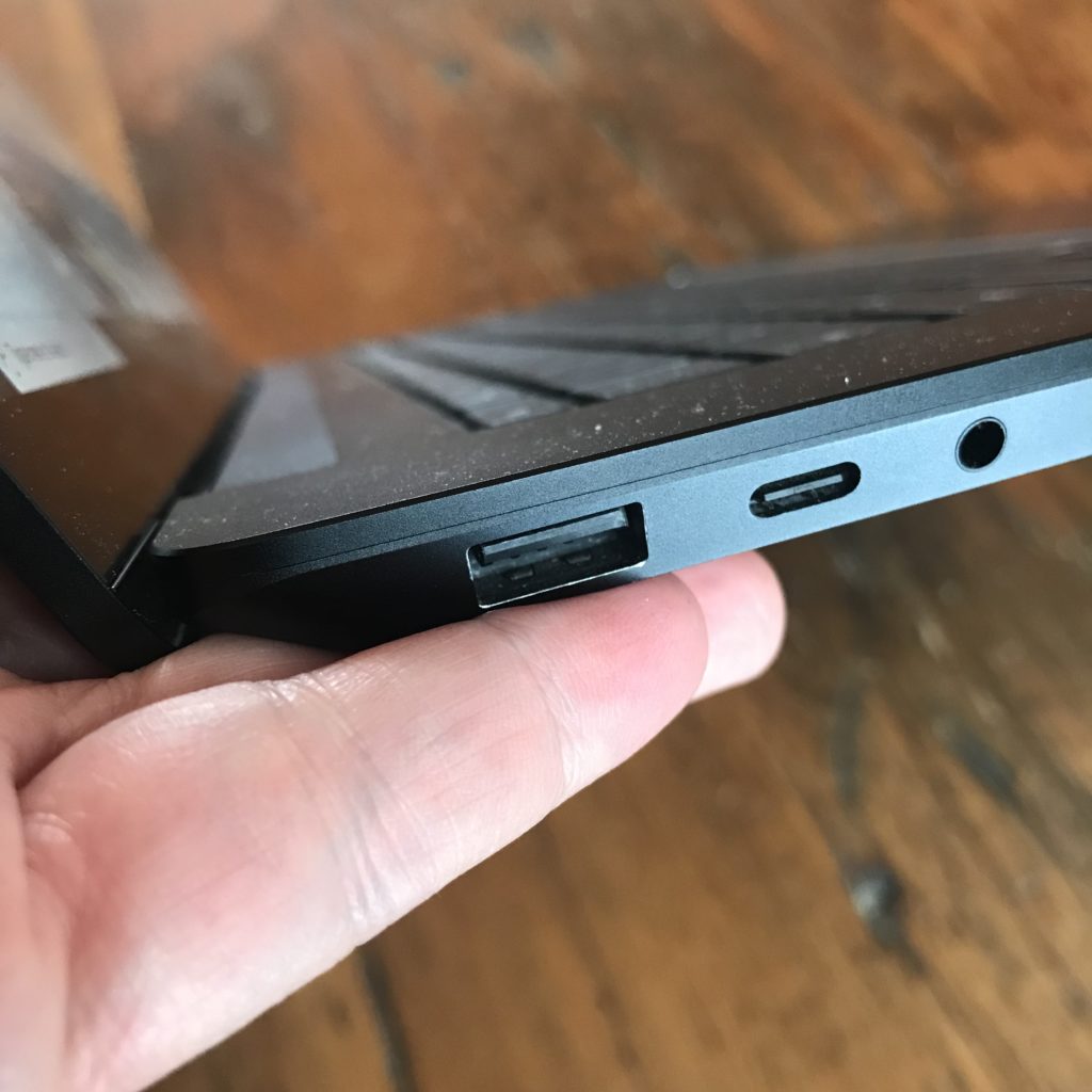
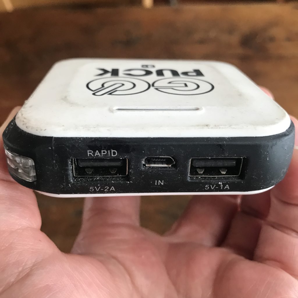
USB ports may also be found on USB hubs, which are devices designed to power several different USB compatible items at once.
Anatomy of USB
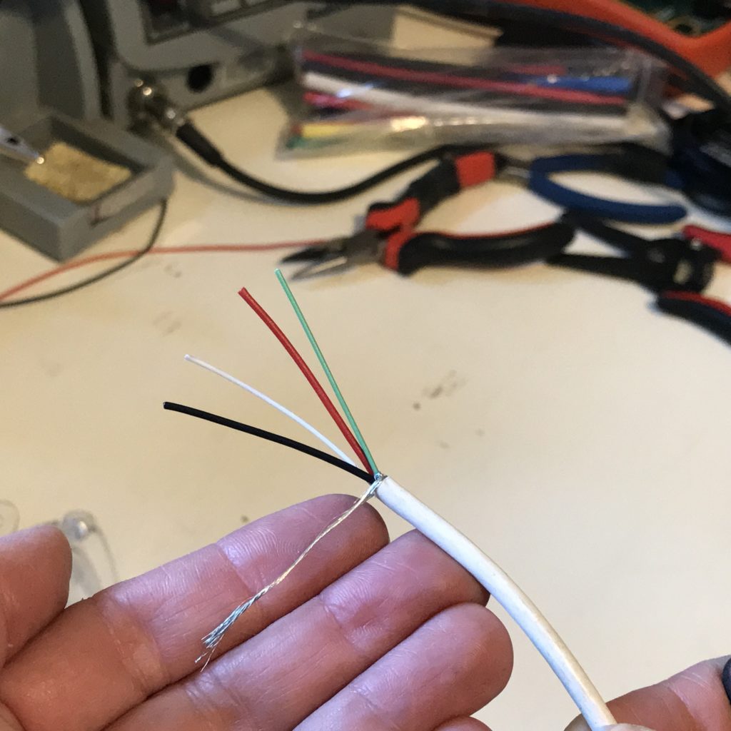
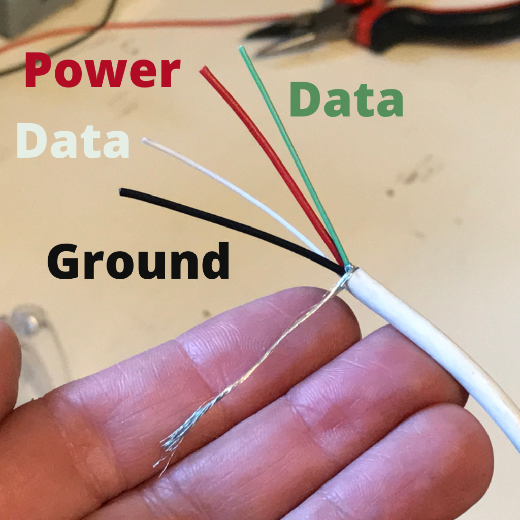
Standard USB connectors contain four metal pads that correspond with specific wires inside of a cable: ground (-), two data lines, and power (+). Ground wires are usually black or blue. Data wires are usually white, gold, or green. Power wires are usually red or orange.
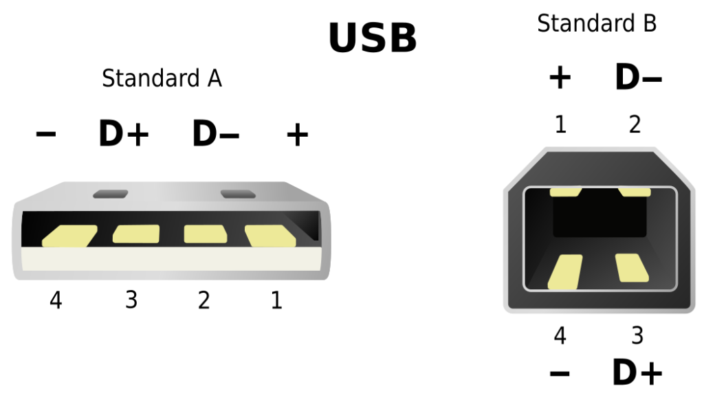
Image Courtesy of Simon Eugster
| Pin | Name | Wire Color | Description |
| 1 | Power | Red or Orange | +5V |
| 2 | D- | White or Gold | Data- |
| 3 | D+ | Green | Data+ |
| 4 | Ground | Black or Blue | Ground |
DIY USB to Alligator Clip Cable
Did you know that the chargers from old smartphones and electronic devices might still be useful? That the cables from broken keyboards, mice, and speakers may be transformed into a portable, sustainable method for powering your paper circuit projects?
Before you can use a repurposed USB cable to power paper circuits, you will have to cut off one end, strip the power and ground wires, and then solder them to alligator clips.
But, before you turn on a soldering iron or start raiding your home’s junk drawer for parts, please read over the following safety tips.
Safety Tips
- Never touch the tip of a hot soldering iron with your bare skin; soldering with a hot iron may lead to accidental burns.
- Always use eye protection when soldering.
- Always ensure good ventilation when soldering; the fumes may be toxic.
- Always test for short circuits with a coin battery, or the continuity function of a multimeter, before connecting your paper circuit to USB power; short circuits may cause overheating that can potentially result in fires, bodily harm, or damage to your home, computer, or project.
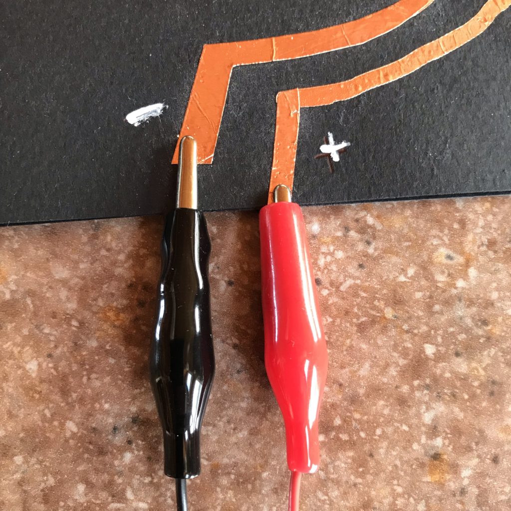
- Always be careful not to reverse the positive and negative leads of your circuit (it’s helpful to label them clearly) when attaching USB powered clips to your project.
- Always prevent the positive and negative alligator clips from touching one another while plugged in, or a short circuit could damage your computer; alligator clips are typically insulated in plastic to help prevent accidental contact.
- Always use resistors in paper circuit projects you plan to power from a USB port, or your LEDs will burn out at 5V. Circuit Sticker LEDs have built in resistors to help eliminate the guesswork.
Materials & Tools
- USB Standard Type-A cable
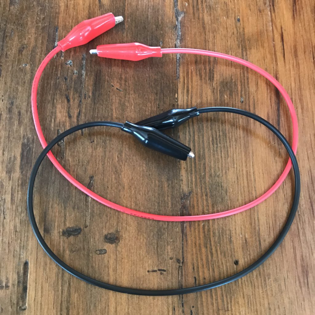
- 2 alligator clips (one red/ one black)
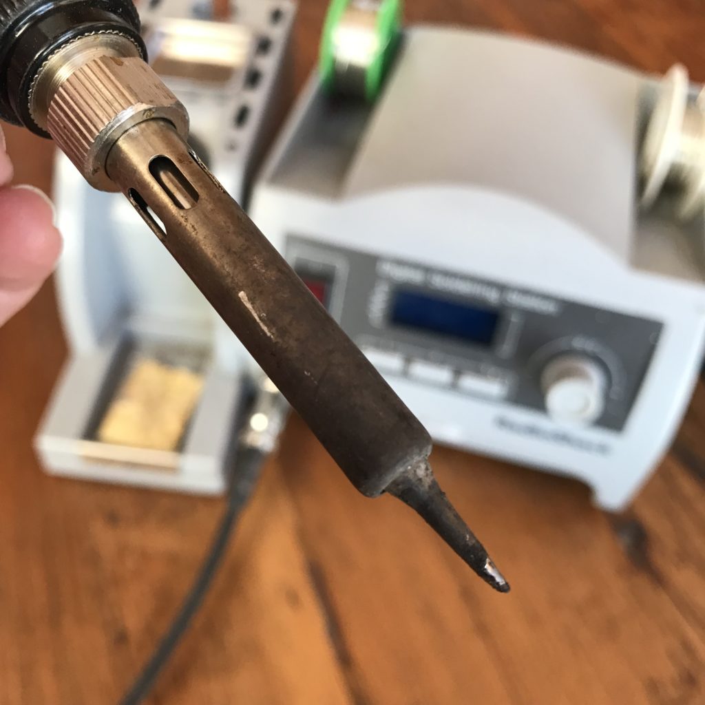
- soldering iron
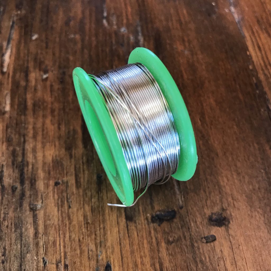
- solder
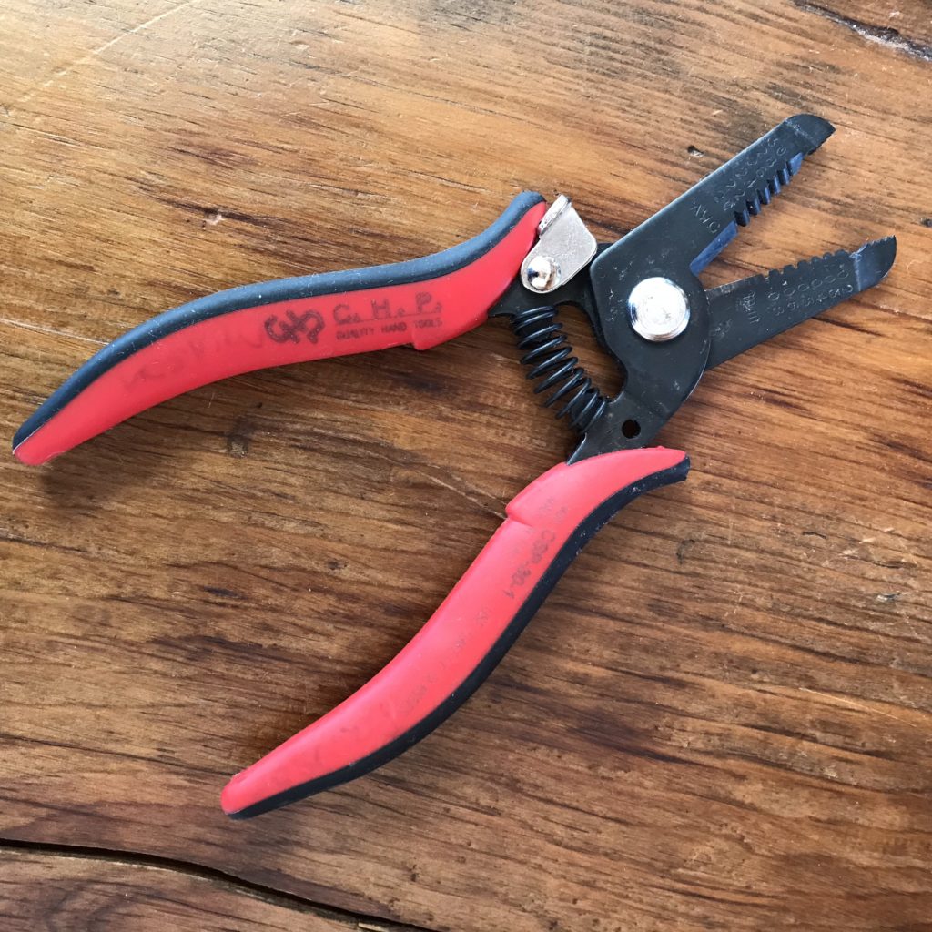
- wire cutters/ strippers
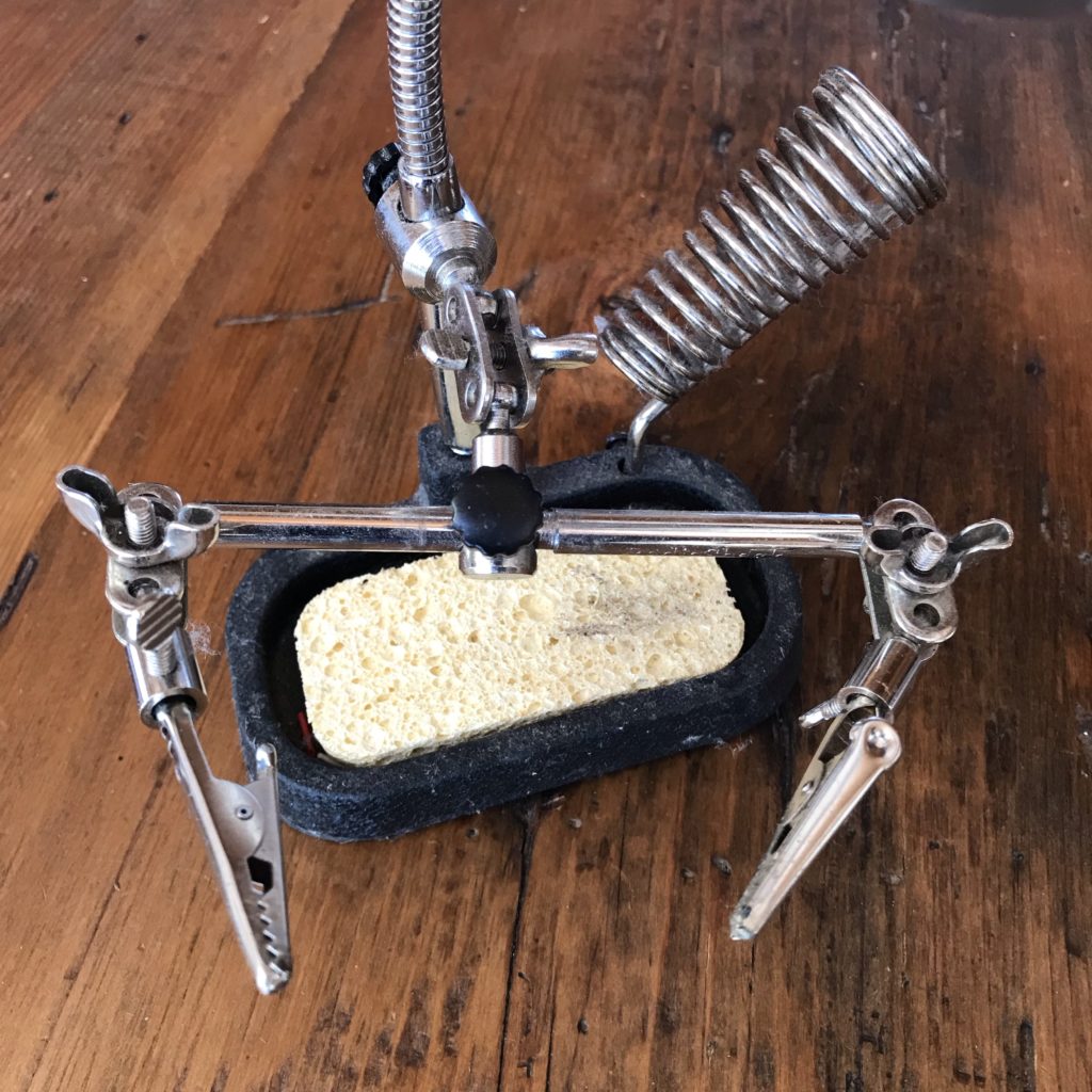
- helping hands
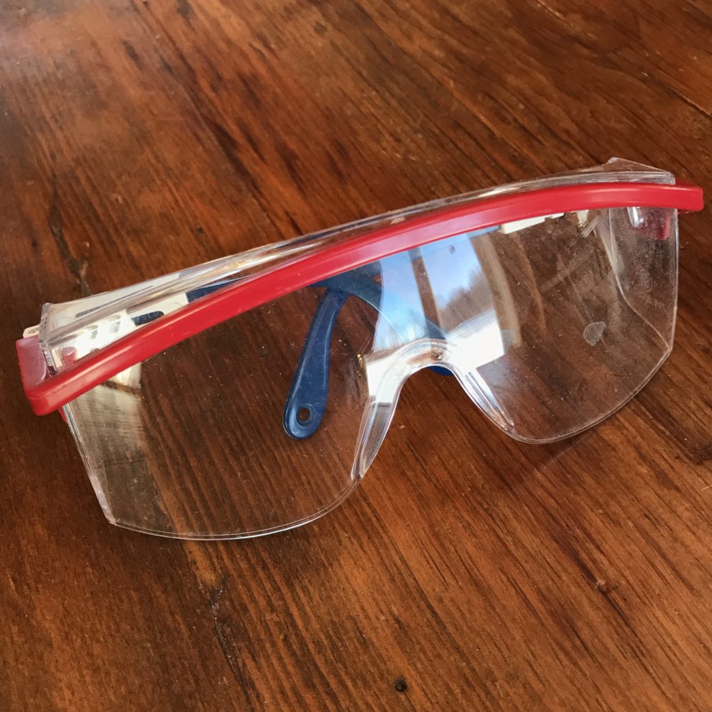
- eye protection
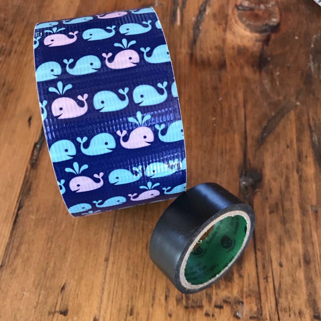
- electrical (or duct) tape
- heat shrink tubing
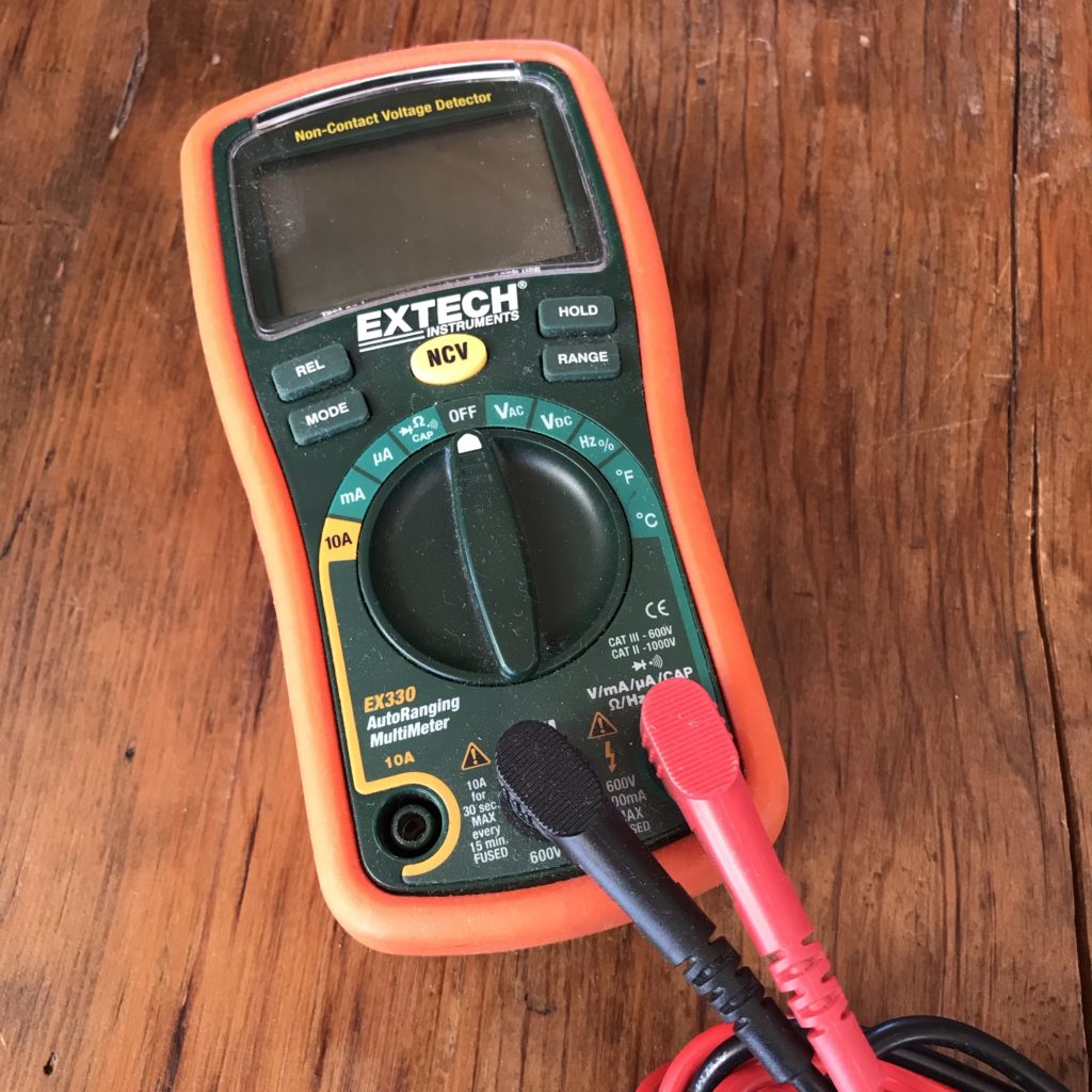
- multimeter (optional)
Directions
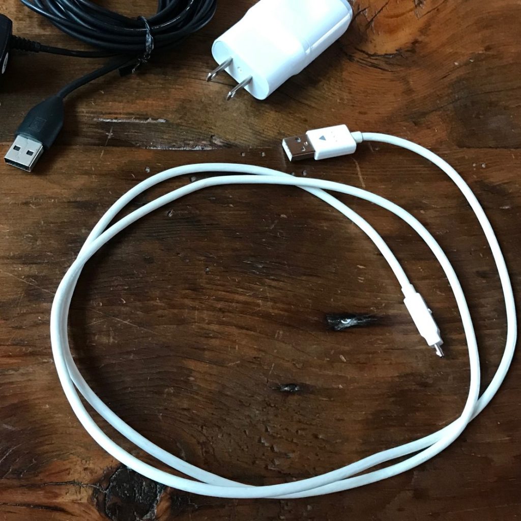
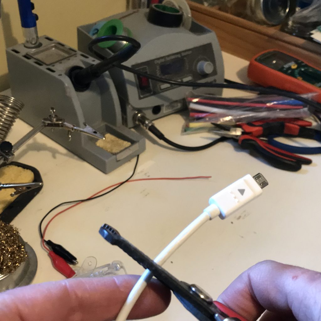
First gather your tools and supplies. Then, locate the Type-A plug (the one on the left) on a suitable cable. You will be keeping that plug and discarding the other.
Cut USB Cable
Using a pair of wire cutters, the next step is to remove the unwanted end of the cable.
Remove Casing
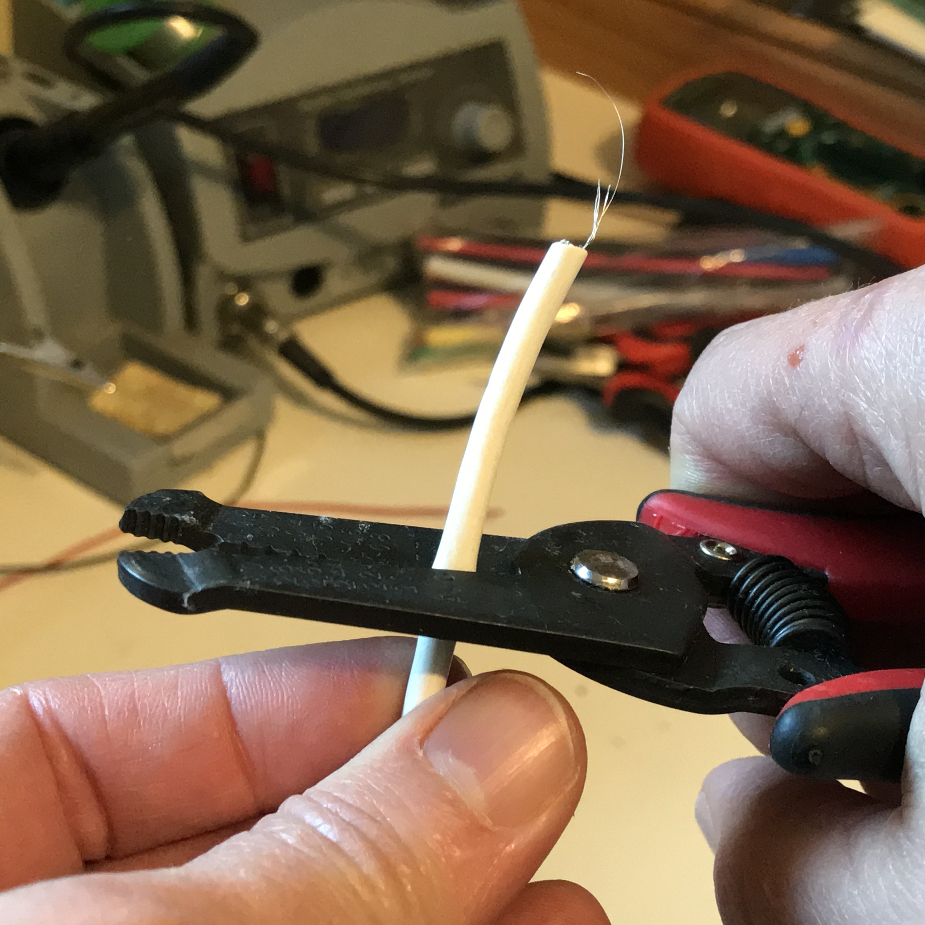
Next, with one end of the cable exposed, you will need to remove some of the protective casing.
Starting about an inch below the exposed end, carefully cut the plastic casing all the way around the cable and pull it off.
If you find an additional layer of aluminum shielding beneath the casing, you’ll need to remove that too.
Prepare the USB Wires
Next, to make them easier to work with, fan out the wires on the USB cable.
Note: While some USB cables have adequate wires inside, some can be excessively flimsy. If you encounter a cable with old, wimpy wires inside, you may need to find a more suitable one.
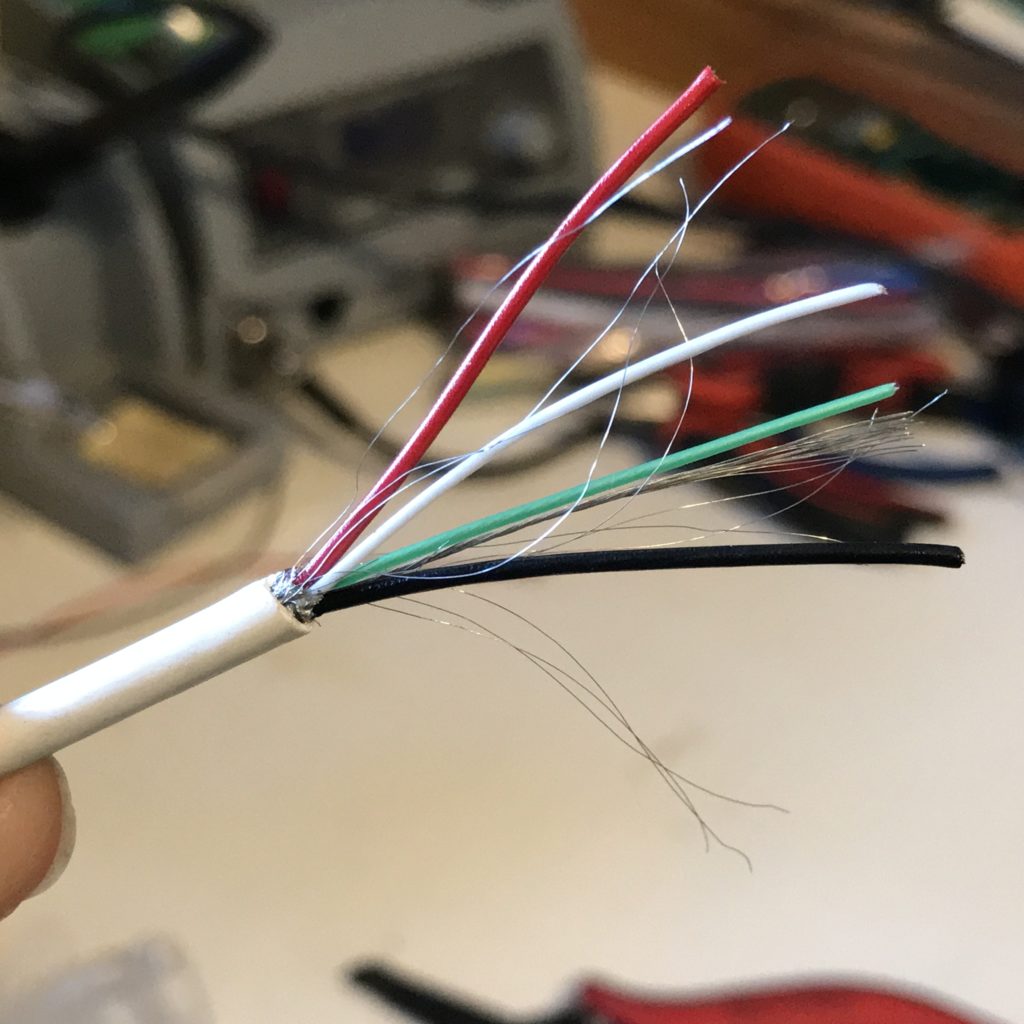
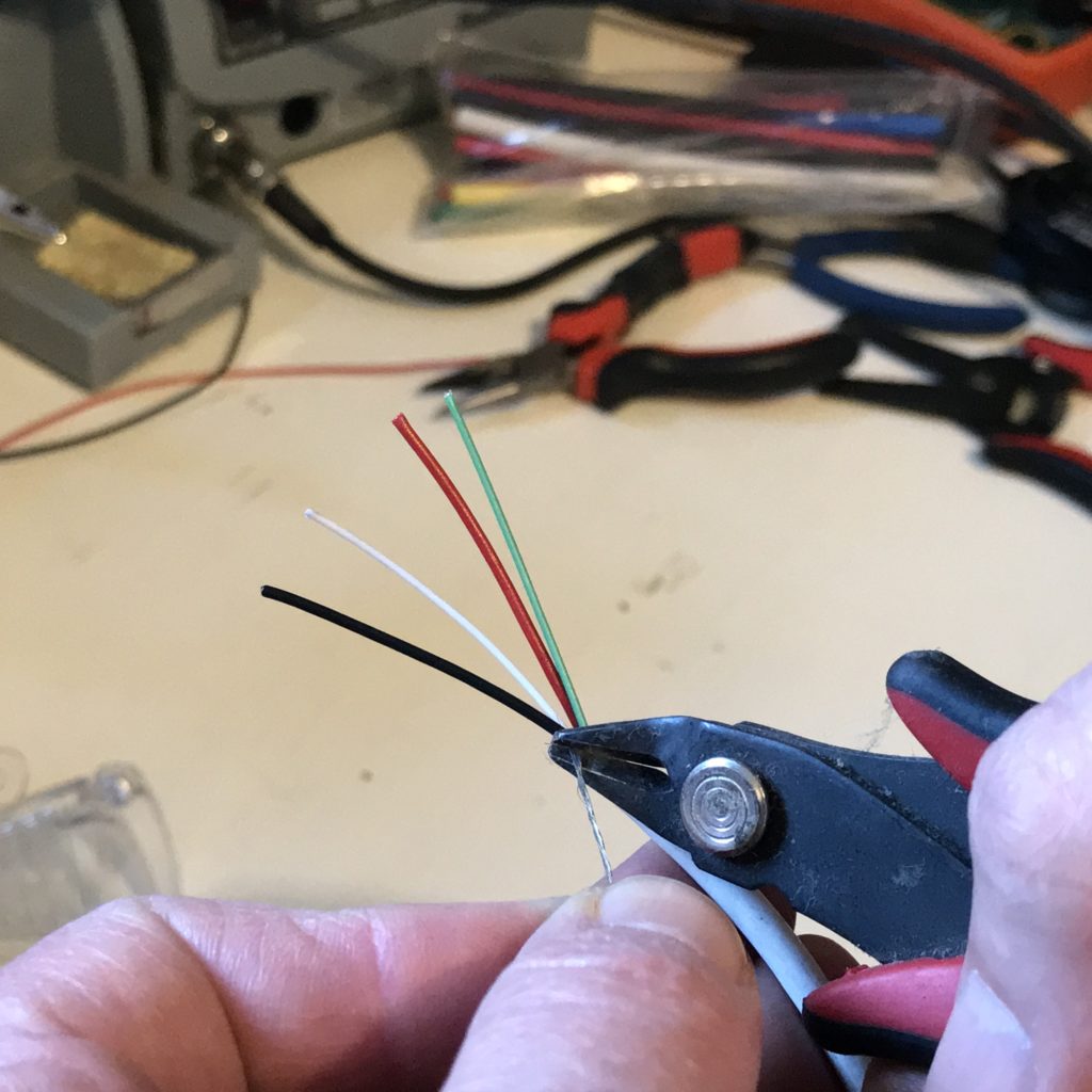
Gather and twist the stray metallic fibers together, making it easier to remove them.
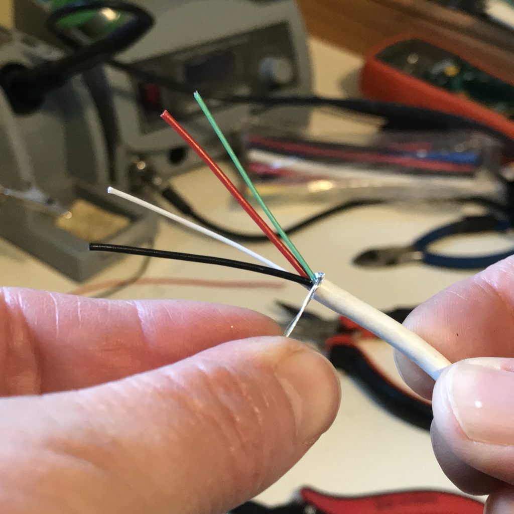
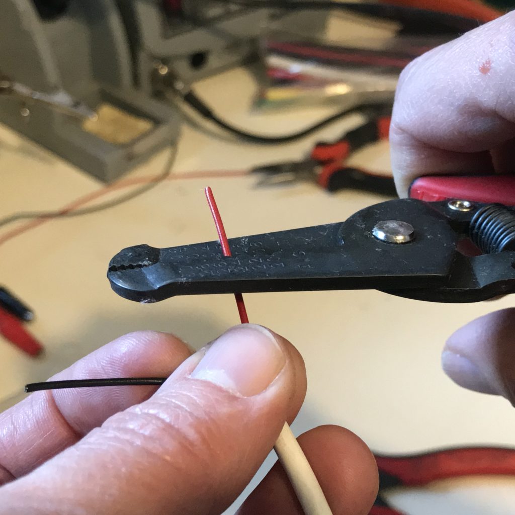
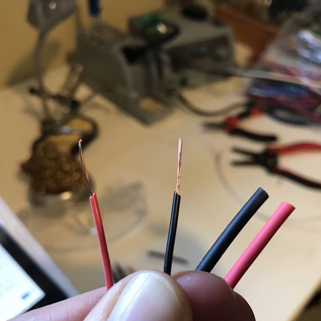
Use wire cutters to remove the twisted metal fibers and both data wires (the white and green ones). Leave only the wires for power (red) and ground (black).
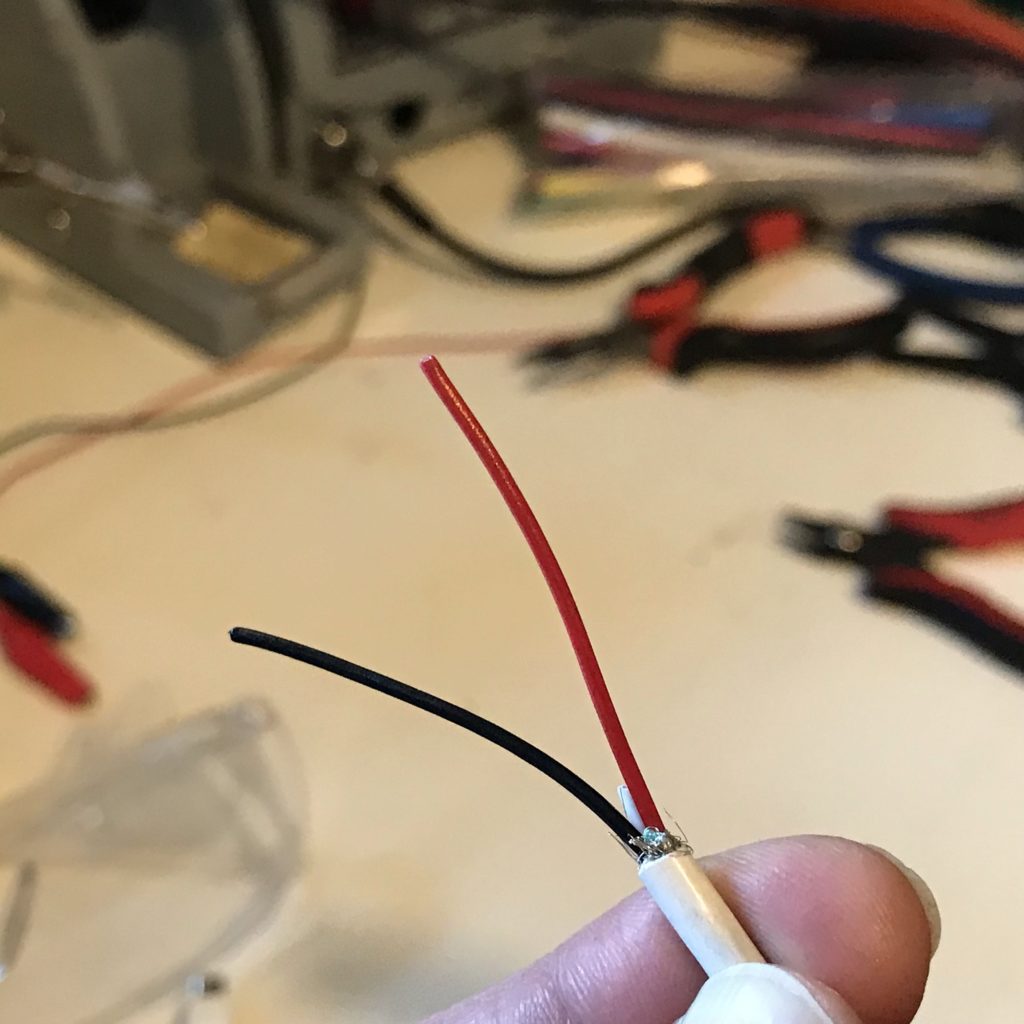
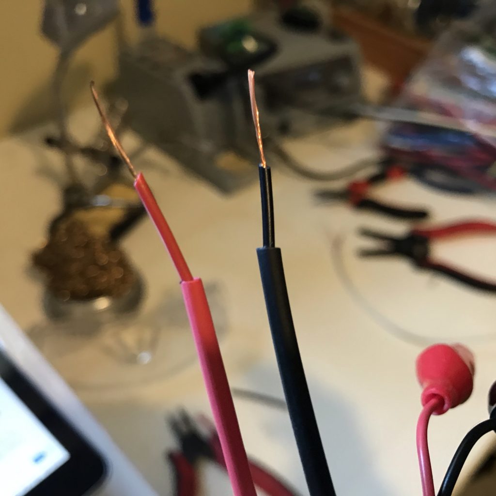
Use wire strippers to remove the plastic coating from at least ½” of the USB cable’s power and ground wires. Afterward, you may need to twist the tips of each wire.
Preparing Alligator Clips
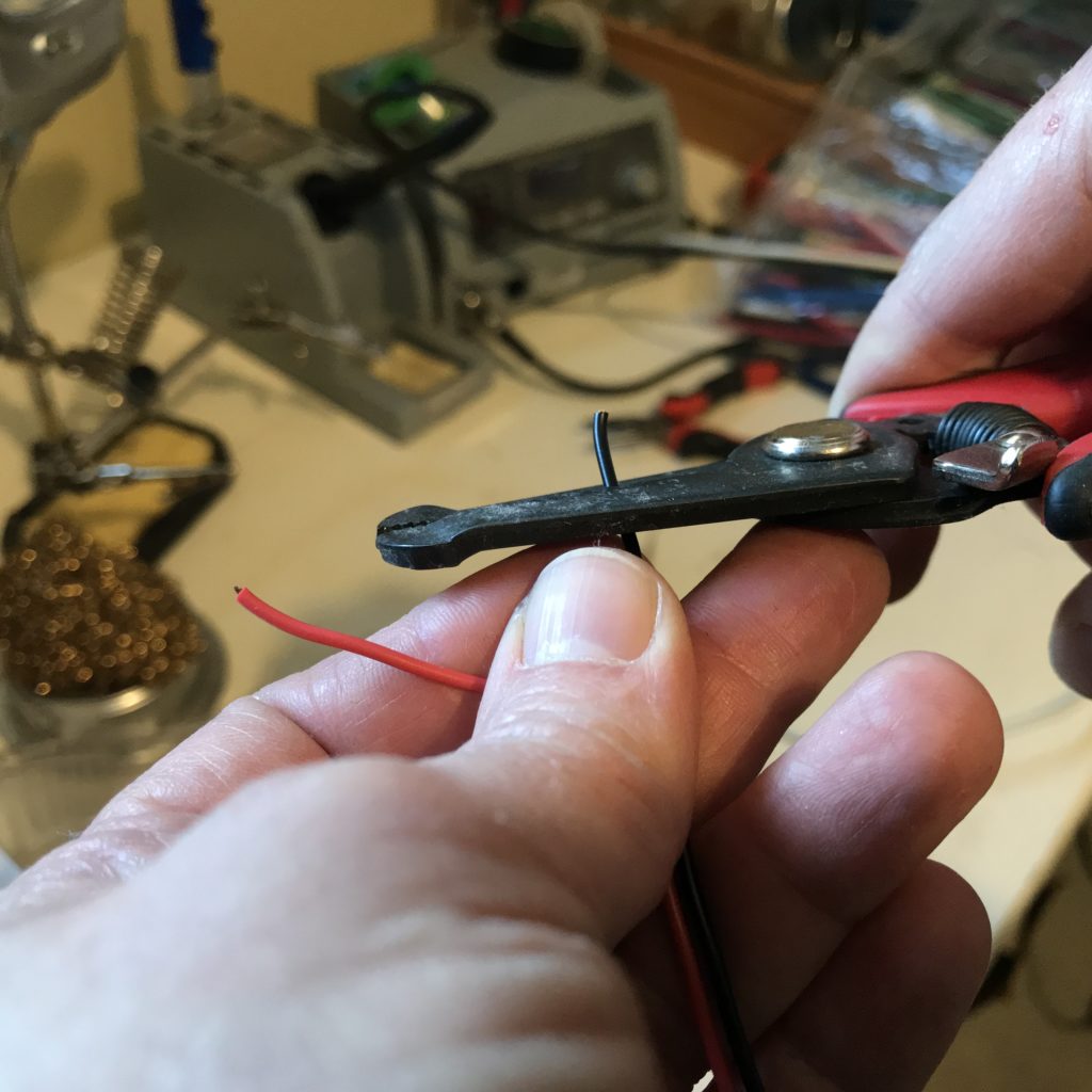
To make it visually easier to determine which wires are positive and which are negative, cut the black and red alligator clips into halves, putting the extras aside for another project.
Then, strip off the plastic coating and twist the exposed wires on both alligator clips.
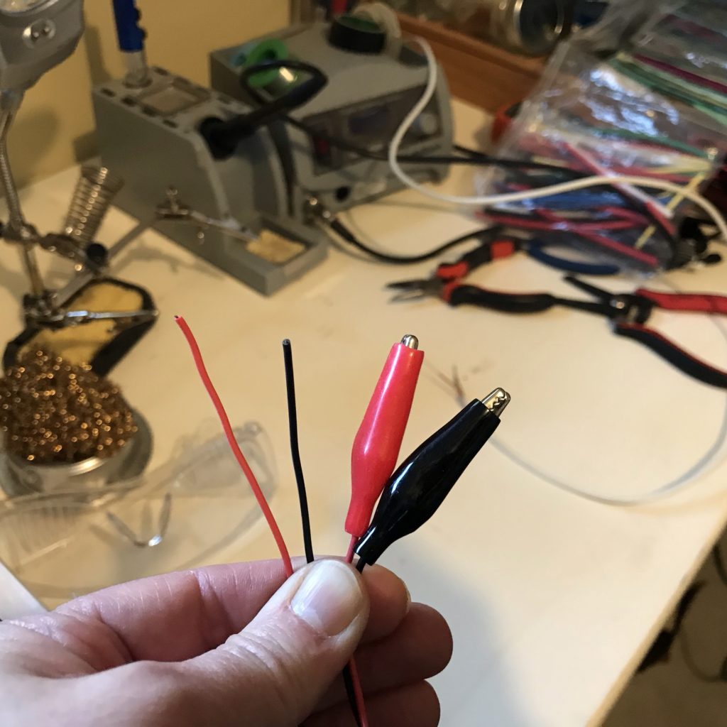
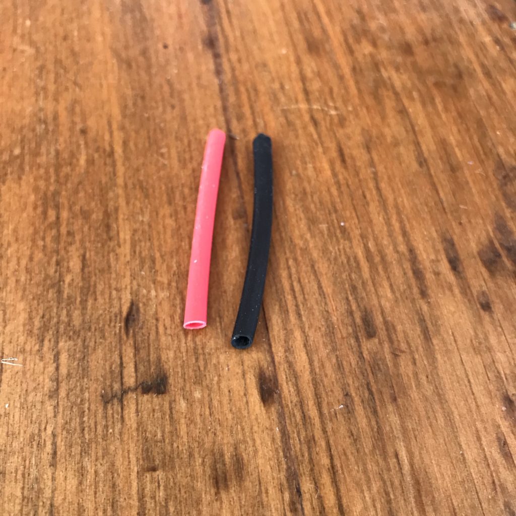
Insert each of the exposed alligator clip wires through a 2”-3” length of heat shrink tubing, ensuring that the tubing will be large enough to slip over the solder joints, but narrow enough to shrink down around the wires.
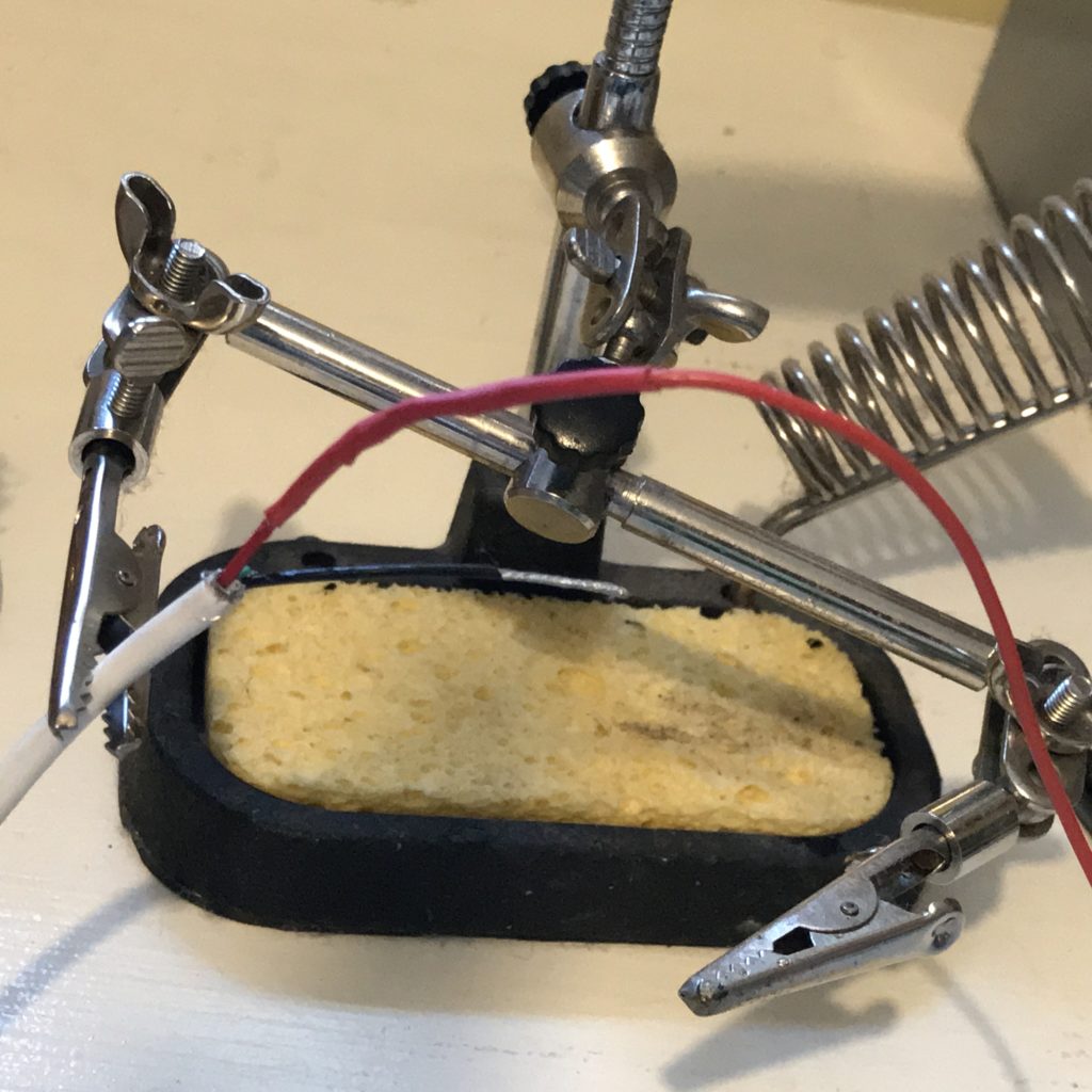
Solder
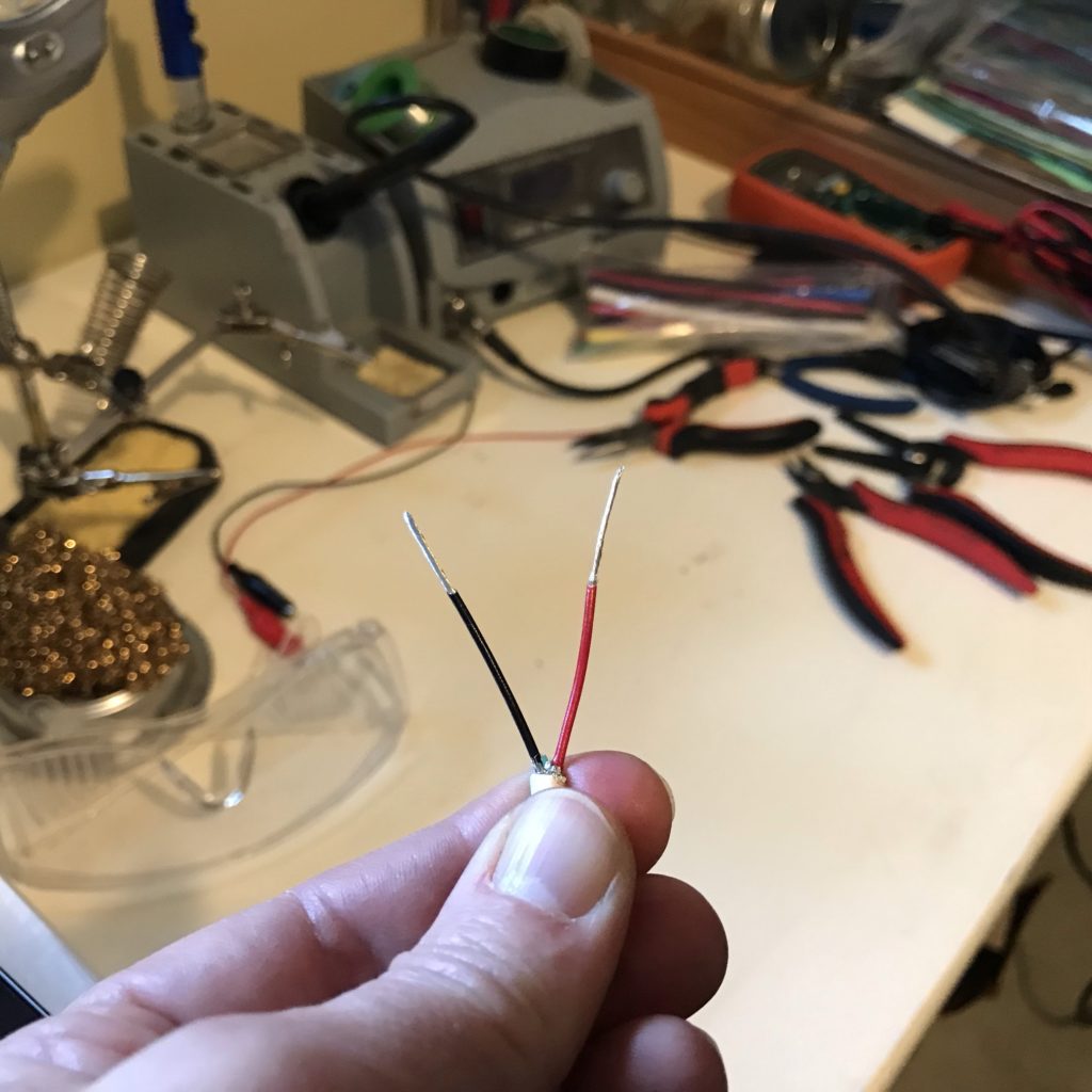
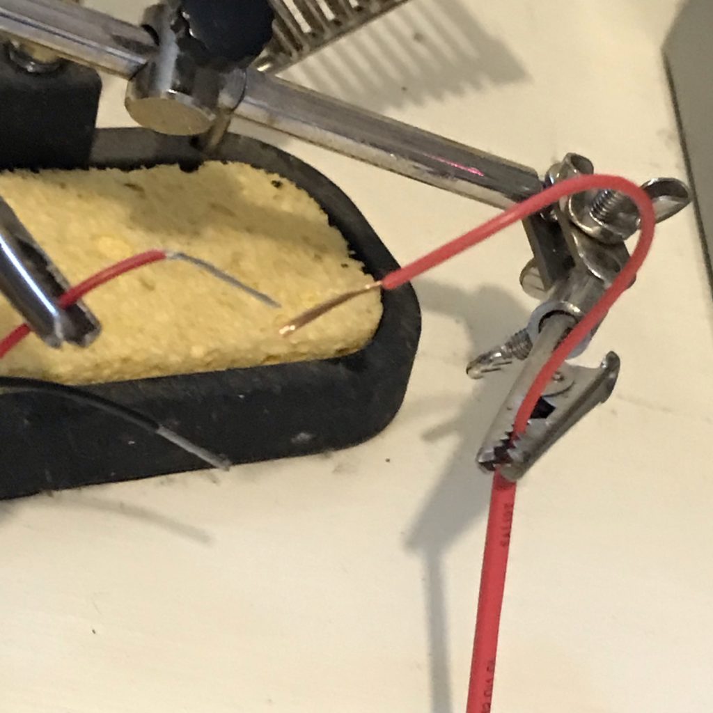
Use a set of helping hands to hold the USB power wire in one hand and the red alligator clip wire in the other. Tin the wires, twist them together, and connect them with hot solder.
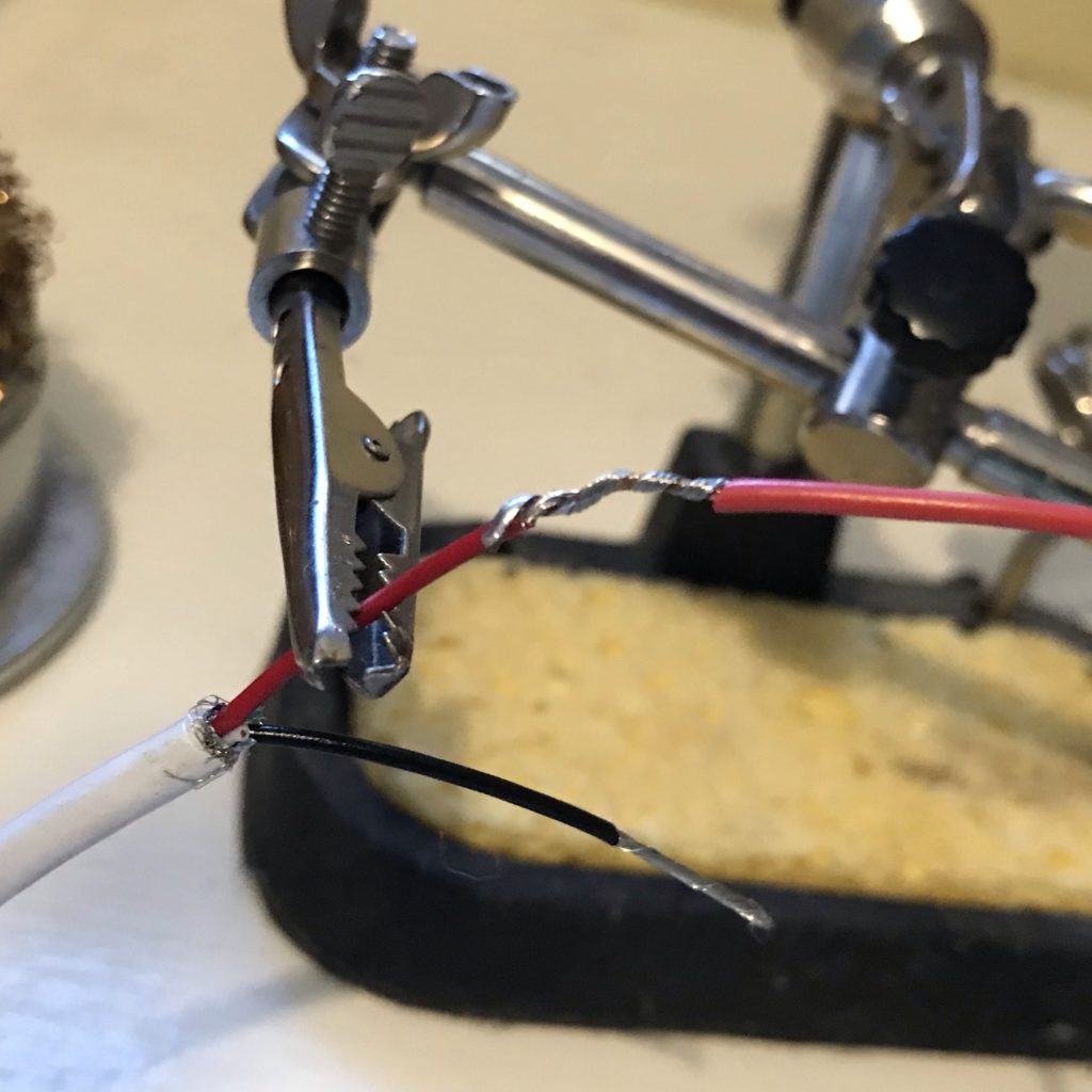
After ensuring a robust connection, slide the heat shrink tubing over the joint and heat it until it wraps securely around the joint. Repeat this process for the ground wire (-) and black alligator clip.
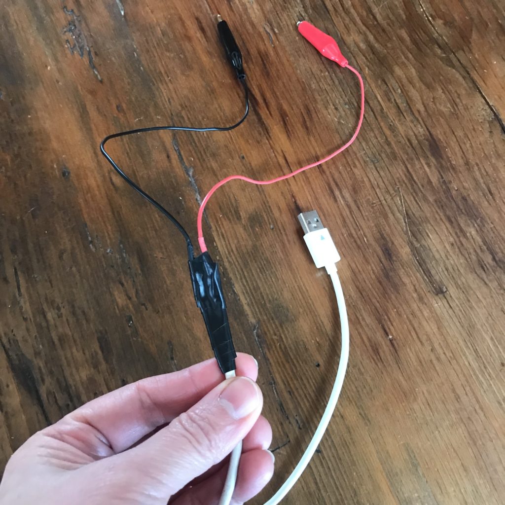
Reinforce the USB cable in the area where you completed the soldering, by wrapping electrical tape between and around the wires, and then your new USB power cable is ready to use!
Tips, Tricks & Call-outs
Remember to test your circuit with a coin battery, or the continuity function of a multimeter, before connecting it directly to a USB port. This is especially important if you are planning to plug your paper circuit directly into a wall adapter or computer.
It’s helpful to clearly label the positive and negative leads of your circuits.
Also be sure to keep the alligator clips insulated and positioned away from one another to prevent them from accidentally touching.
What Projects Might You Power with USB?
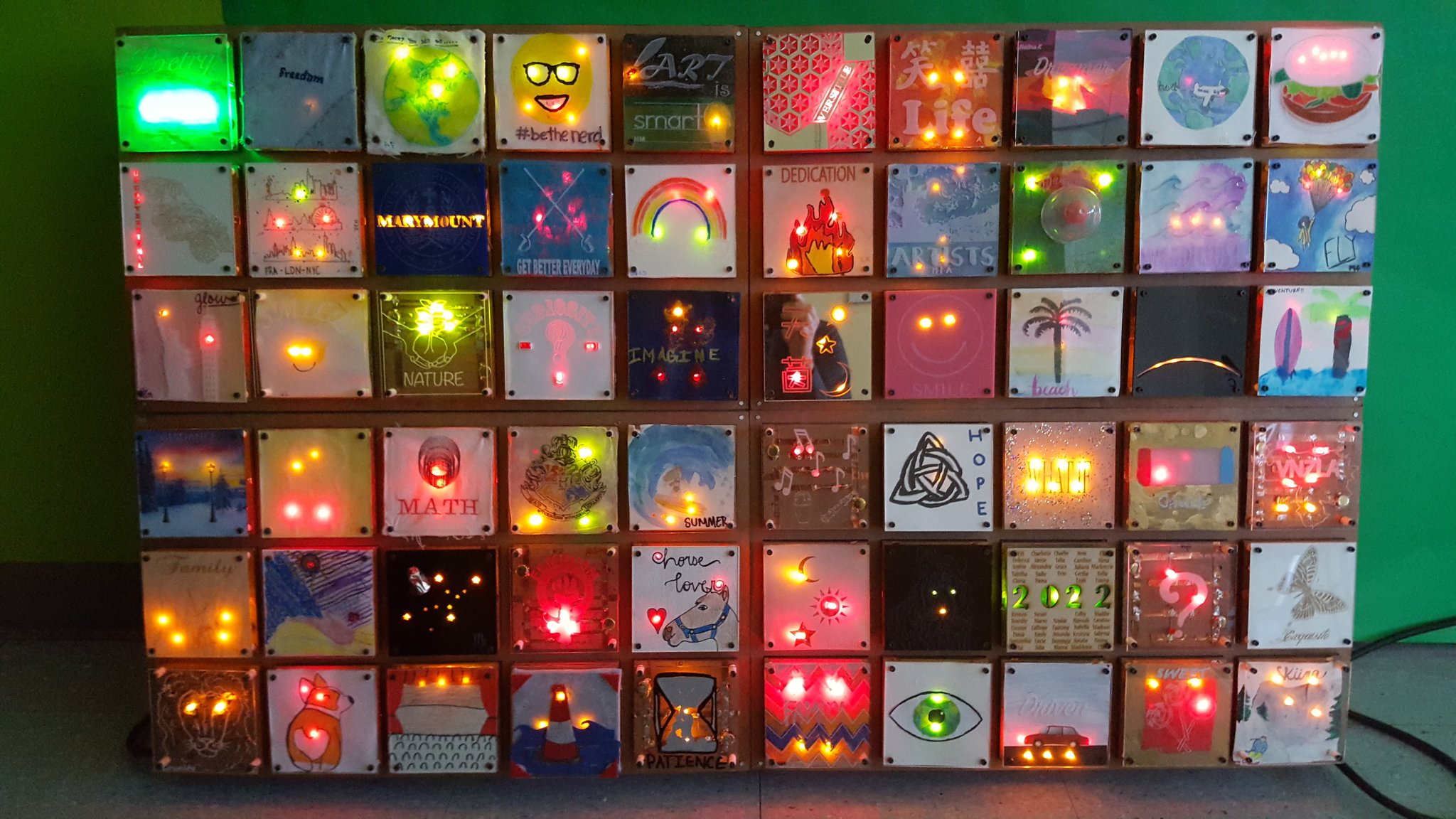
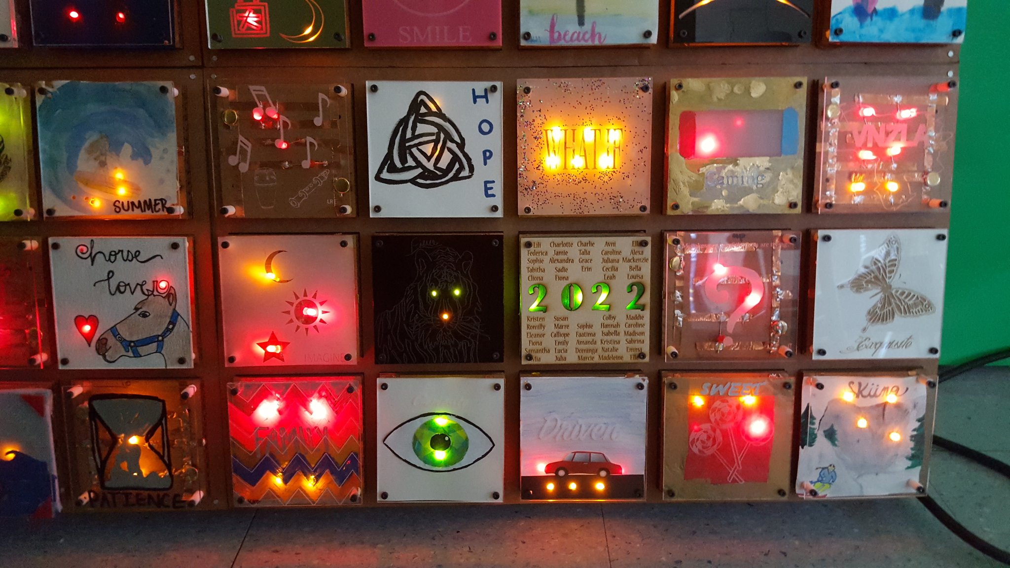
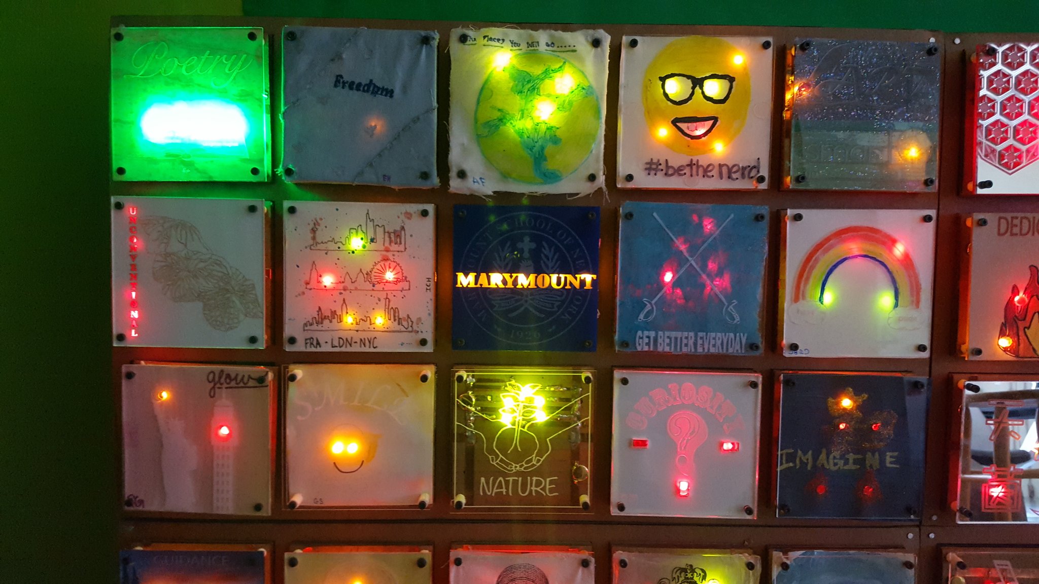
For a stunning example of a collaborative “circuit quilt” connecting 60 individual circuits into a single, glowing display, check out the work of students from Marymount School in NYC, under the instruction of educator Jaymes Dec (see gallery below)!
For additional inspiration, check out the Featured Projects (page 141) in our Paper Circuits STEAM Educators Guide. Several projects in the guide, which have been programmed using a Chibi Chip, are powered via USB; these include collaborative murals, a paper city, and even an accordion book.
Or, What About A…
- collaborative bulletin board
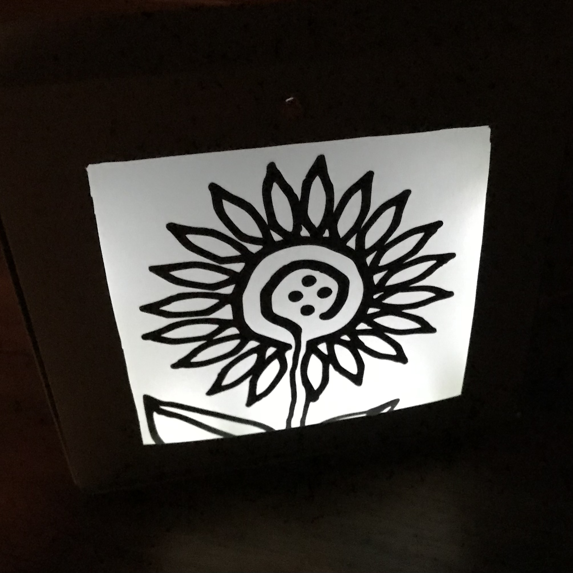
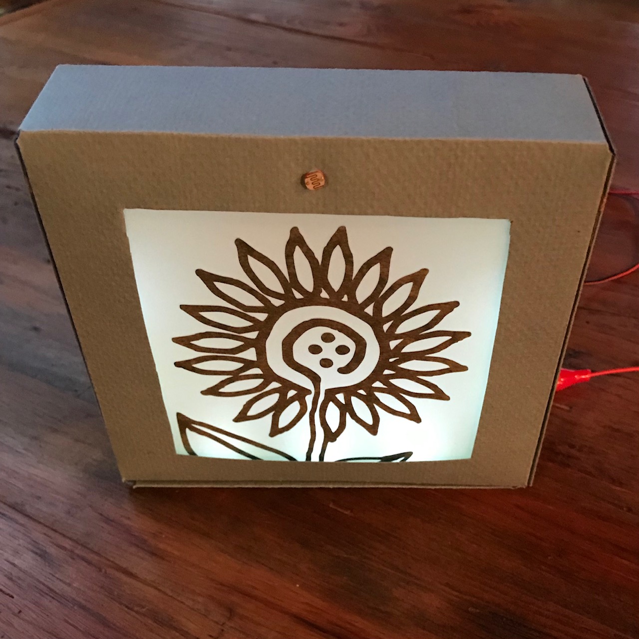
- paper lamp or night light
- light up wall canvas
- light up shadow box
- light up tunnel book
- window art
Gallery

Similar Posts You Might Enjoy
Night Light

In this tutorial, you’ll learn to use copper tape and sticker circuits to make a night light that reveals a secret image when you turn it on!
Haunted House
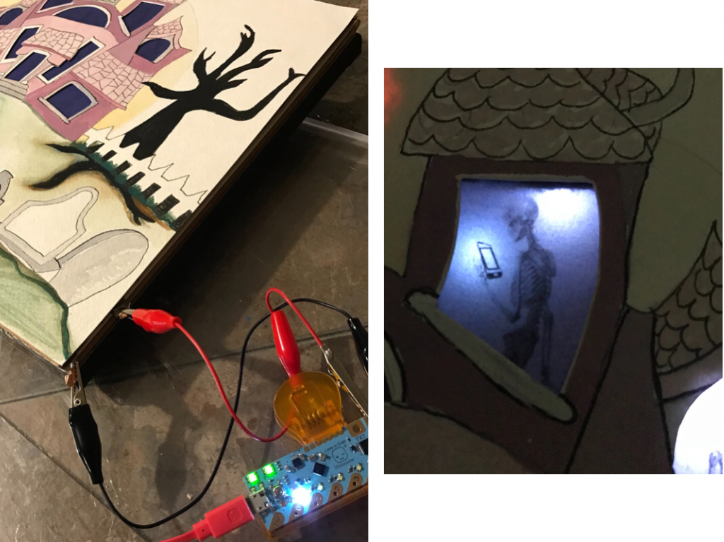
In this set of tutorials, you’ll learn how to use flaps of pressure sensitive conductive plastic to add special effects your paper to circuit projects.
Tickytown
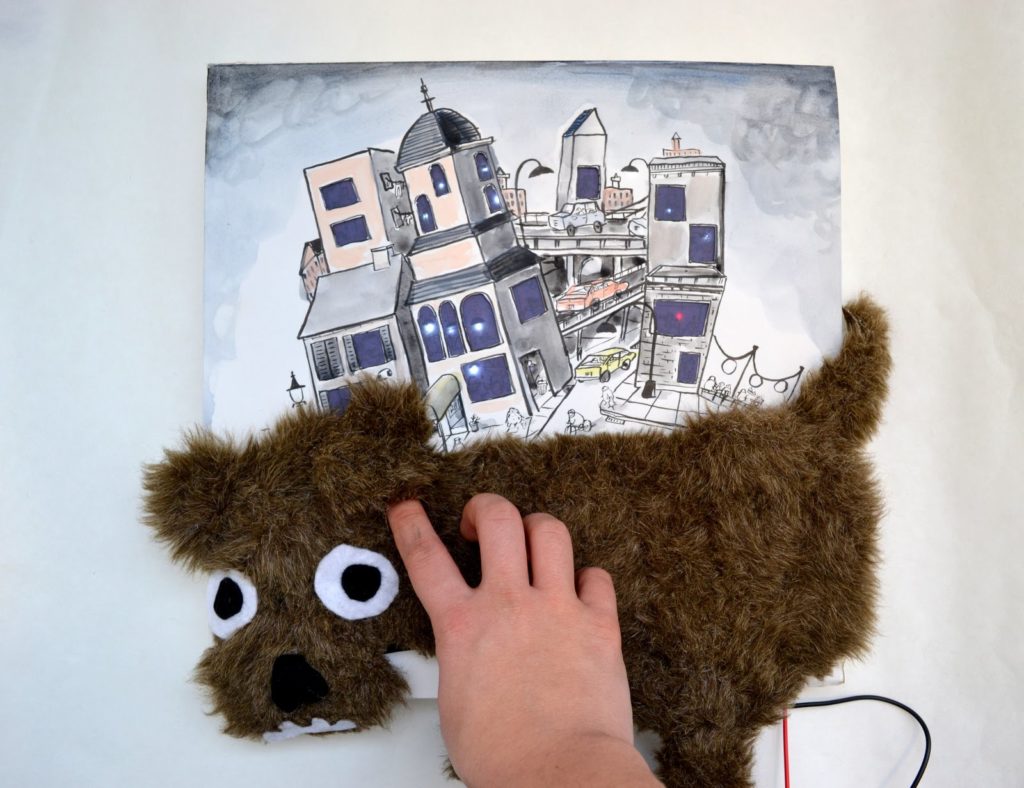
Artist K-Fai Steele discusses her interactive work, featuring a light-up canvas, some pressure sensors, and an itchy dog.