The continuity feature of a multimeter allows you to test for conductivity of materials and trace where electrical connections have been made (or not made). When working with paper circuits, the continuity function of a multimeter is useful for locating wonky connections (joints that should be well connected, but aren’t) and unintended connections (parts that should not be connected, but are).
In other words, the continuity function of a multimeter will help you test for short circuits, locate these potential trouble spots, and make repairs that allow your circuit to work safely and efficiently.
If you’re planning to switch out coin batteries for USB power in a paper circuit, a multimeter is especially helpful for ensuring that it is free from weak connections and unintended ones.
Tools & Materials
- A multimeter
- A circuit that may or may not work (with the battery disconnected)
- Conductive Fabric Tape Patches (for quick, reliable repairs)
Prep Your Multimeter
- If you are using an autoranging multimeter, the first thing you need to do is plug the red cable into the V/mA/CAP (aka. VΩmA) port and the black one into COM. If you are using a manual multimeter, you’ll be plugging the red cable into the VΩ port and the black one into COM.
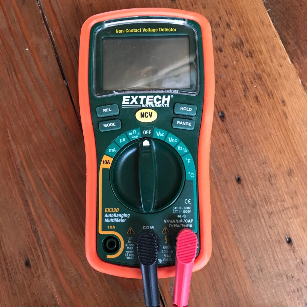
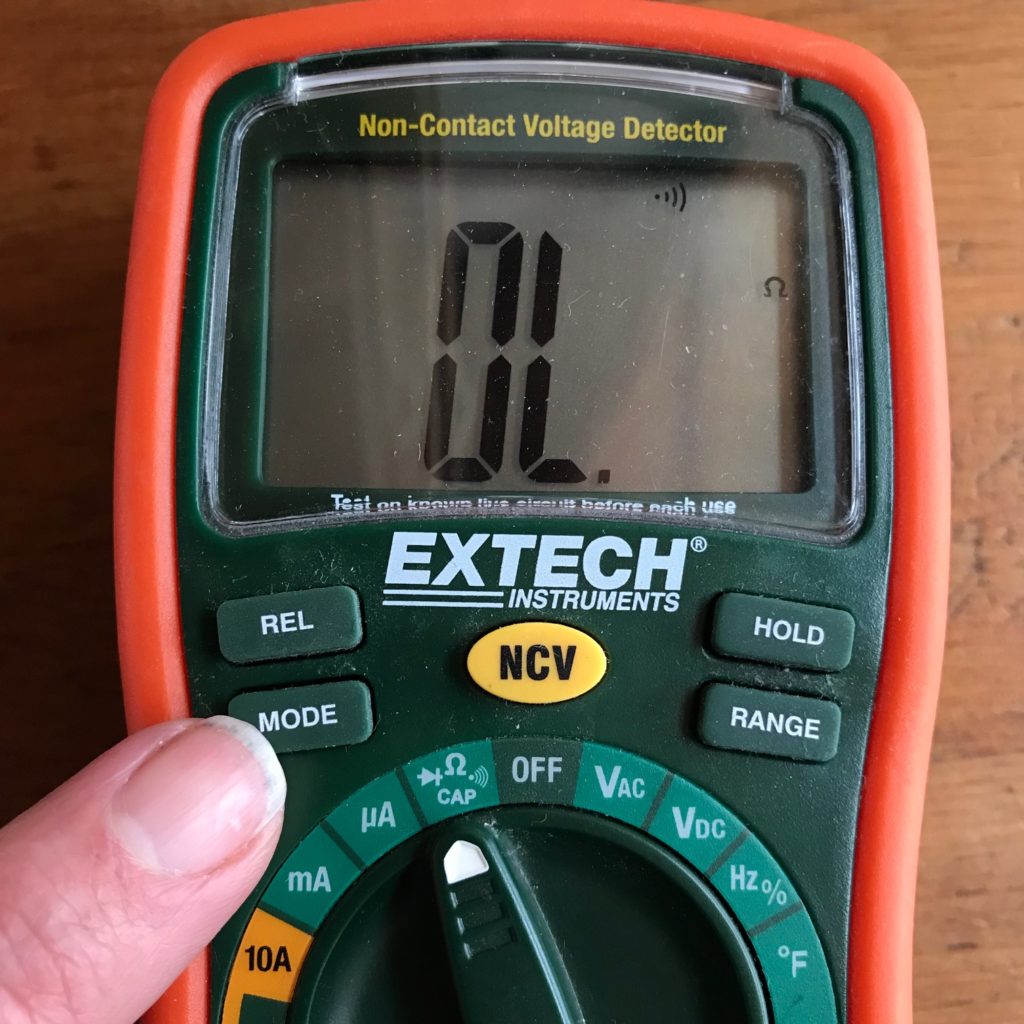
2. To enter continuity mode, turn the dial to the continuity symbol, which will resemble sound waves emerging from a little speaker, or a symbol for a musical note (♫). If you are using an autoranging multimeter, you will also need to press the “mode” or “select” button a few times until the symbol also appears on your screen.
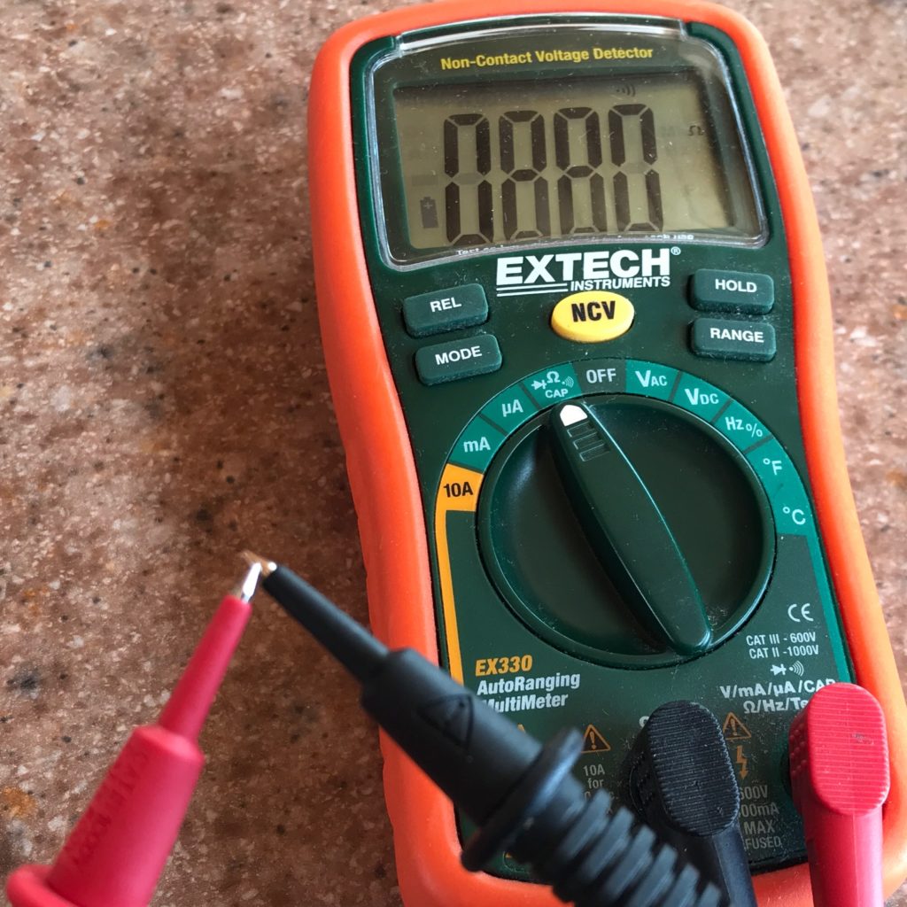
3. Now, touch the exposed metal tips of the two probes together. You should hear a beep or tone, signifying that the probes are connected (that they have continuity). If you hear the beep, you are now ready to test your circuit for electrical connections that have been made, or not made.
Testing for Wonky Connections
Weak, wonky connections within a circuit might cause your LEDs to flicker, glow weakly, or function unpredictably. A wonky connection, which lacks continuity within a conductive path, is a type of short circuit.
Faulty connections within a conductive path occur when two pieces of conductive material are not adequately joined together. For example, wonky joints can occur when two pieces of copper tape are connected together without a sufficient overlap, if there isn’t enough pressure between the pieces, or if the adhesive between them is not conductive enough. Faulty connections (particularly in copper tape) also occur in hinged areas, where frequent folds or bends may result in small cracks that are barely perceptible to the eye.
Step 1: Disconnect From Power
The first step in testing for wonky connections is to ensure your multimeter is in continuity mode and that the circuit you are testing with it is disconnected from its power source. If you haven’t already done so, remove the battery from your circuit.
Step 2: Test for Continuity
To test for continuity, position the multimeter probes on both sides of the connected area or joint that you want to test.
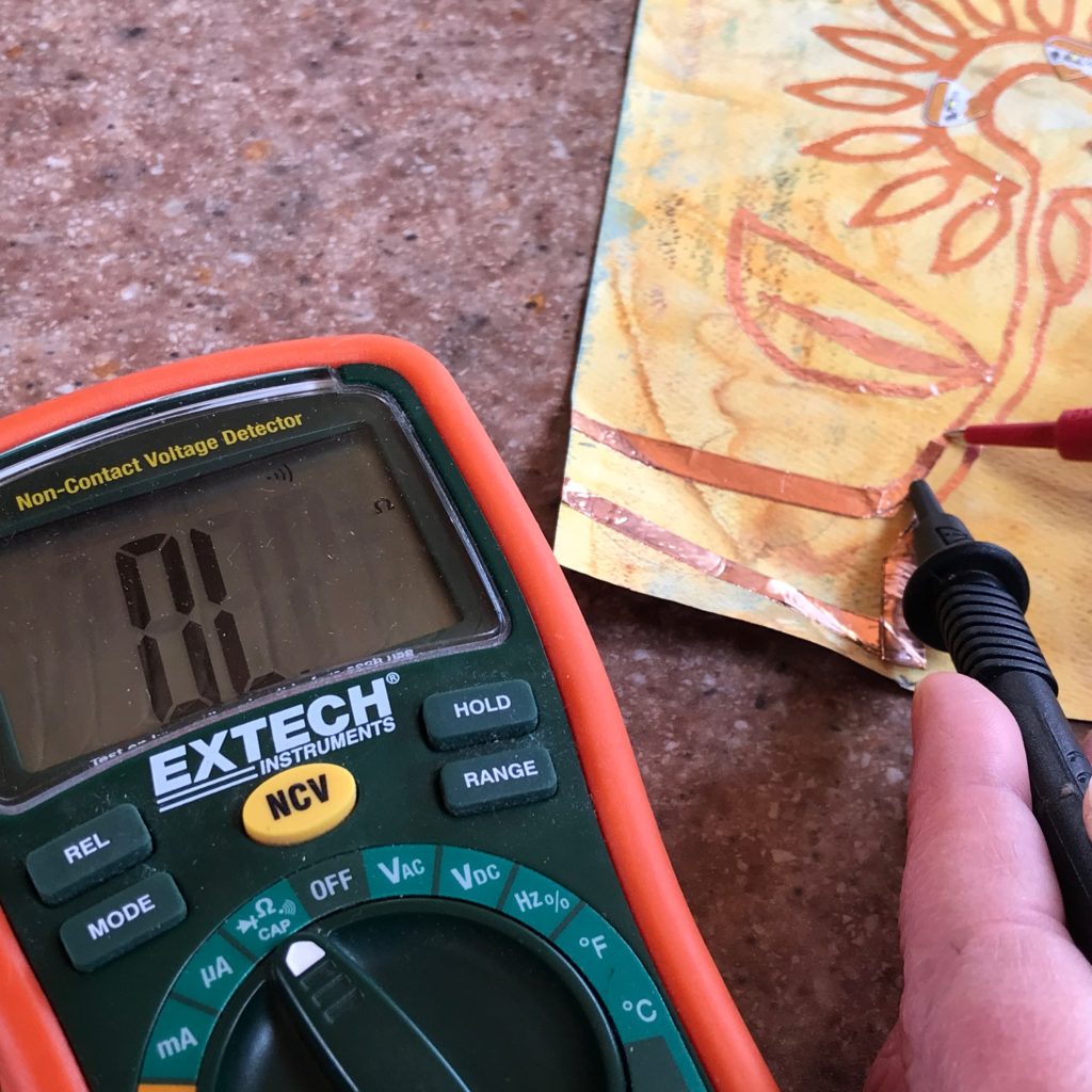
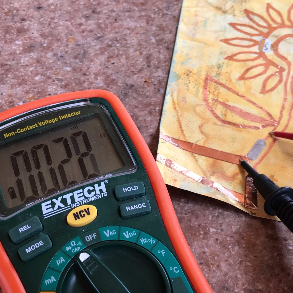
If you hear a faint or disjointed tone, or no sound at all, the connection (continuity) is weak and needs to be repaired. In the image above, the area where two pieces of copper tape have been joined together is not well connected.
The absence of a tone (and a screen displaying 0, rather than a measurement of conductivity) confirm that this joint is not continuous; there is no electrical connection between the traces.
Step 3: Make Repairs & Test Again
If you discover a weak, wonky connection where a strong one is desired, try applying pressure to areas where conductive traces overlap to strengthen the bond, and/or apply a Conductive Fabric Tape Patch to the impacted joint to reinforce it.
If you hear a continuous beep during your test, the connection (continuity) is strong! Congratulations!
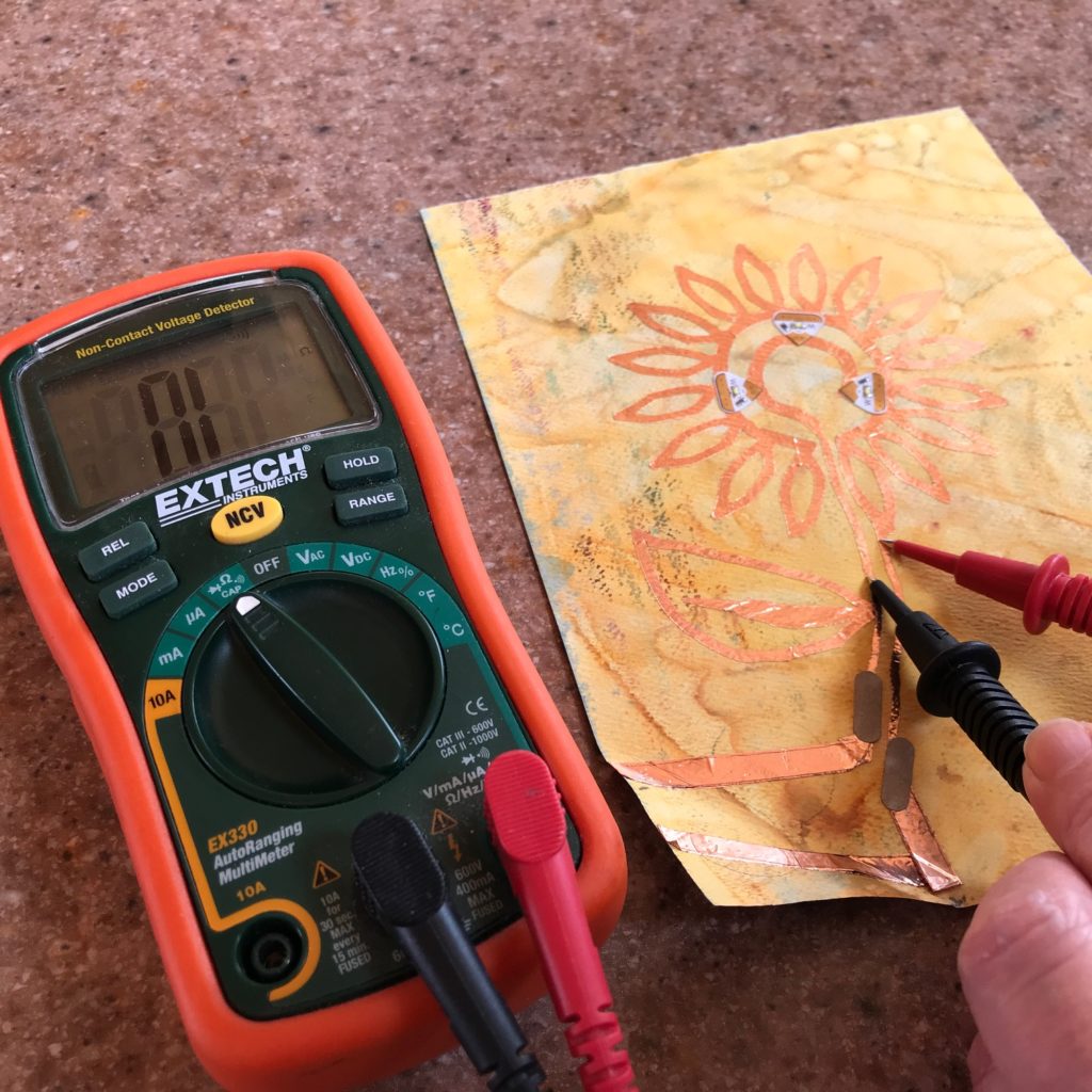
In the image below, the addition of a Conductive Fabric Tape Patch fixed the problem! The presence of a continuous tone (and a screen that is displaying a measurement of conductivity) confirm that this joint is continuous; there is a sufficient electrical connection between the traces.
Identifying Unwanted Connections
Another type of short circuit occurs when continuity between two traces occurs where it should not.
If the positive and negative traces in your circuit come into accidental contact with one another, for example, your circuit won’t work properly and might overheat.
Step 1: Disconnect from Power
The first step in testing for wonky connections is to ensure your multimeter is in continuity mode and that the circuit you are testing with it is disconnected from its power source. If you haven’t already done so, remove the battery from your circuit.
Step 2: Test for Continuity
To determine whether your circuit has continuity where it should not (such as between the power and ground traces, which should not be touching), position the red multimeter probe on the positive trace and the black probe on the negative one.
If there is no sound, the traces are not touching. Congratulations! The absence of a tone (and a screen displaying 0, rather than a measurement of conductivity) confirm that this joint is not continuous; there is no electrical connection between the traces. In this case, silence is golden!
If you hear a continuous beep, however, or even a faint, disjointed tone, the traces are touching, continuity has been detected, and a short circuit is likely present.
Step 3: Make Repairs & Test Again
If you discover that your circuit has a short, or continuity where there should be separation, look carefully at your circuit to determine where accidental overlap of the traces may have occurred.
Might you have reversed the polarity of one of your LEDs, or forgotten to add an insulating bridge between your power and ground traces?
Once you’ve identified the source of the unwanted electrical connection, make adjustments and test your circuit again.