Spooked in a Blink
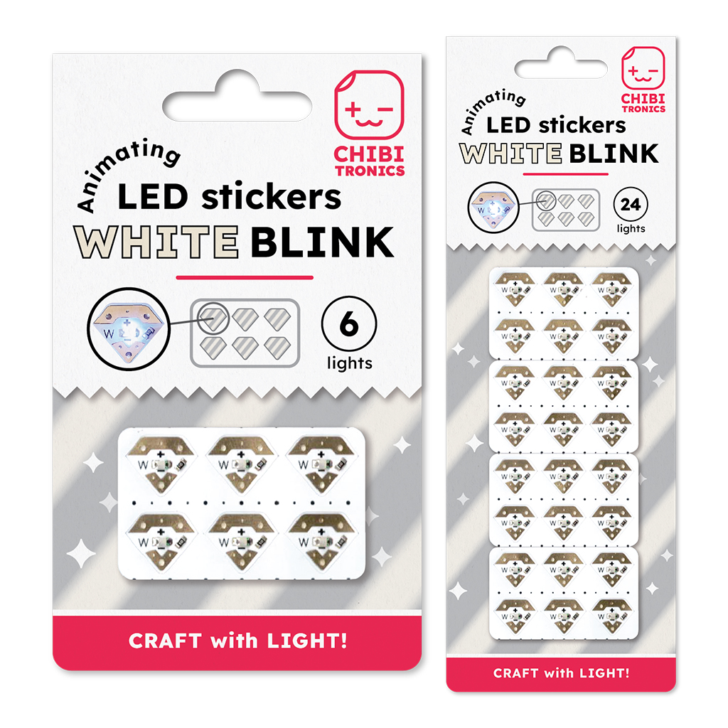
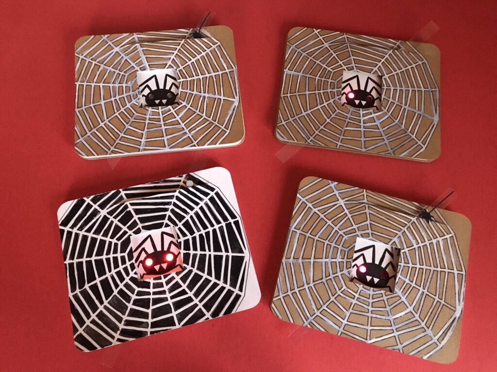
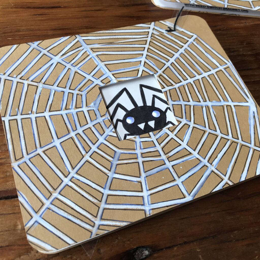
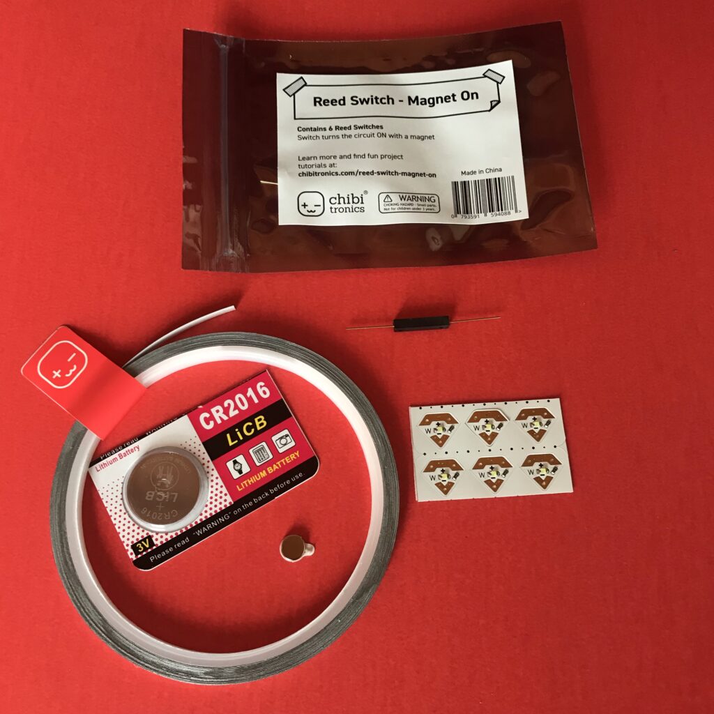
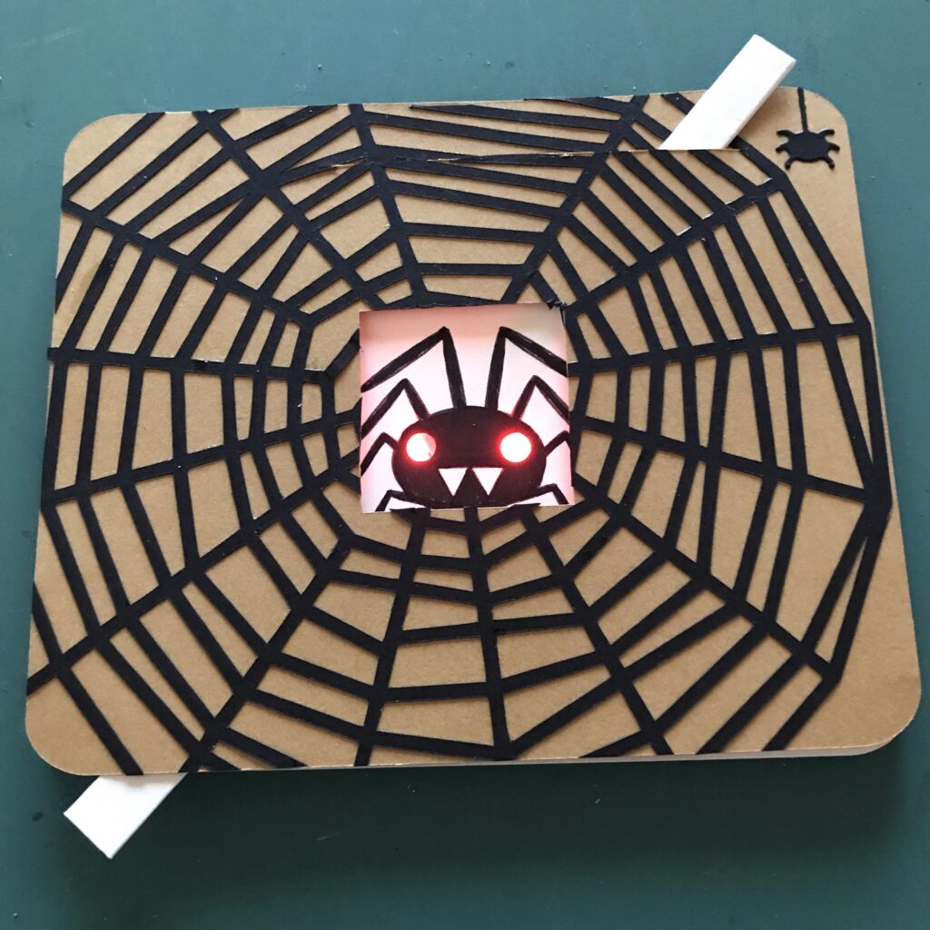
In this tutorial, featuring our new White Blink Animating LED stickers (Image 2a), I’ll show you how to make a mechanical card that reveals a spooky, blinking spider whenever you move a lever (Image 2b).
While this tutorial originally used a traditional coin cell battery, an updated circuit diagram using our new Launchpad Battery has been added.
Make a Mechanical Card Light Up
Video
Related
Categories
Animating LED, Paper Craft
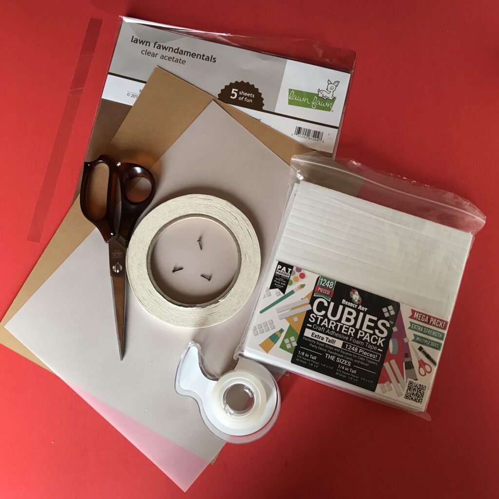
Materials & Tools
Electronic Supplies
NOTE: A Chibitronics Craft with Light Kit contains some of the electrical components required for making a Spooky Spider Diagonal Dissolve Card.
- 2 Chibitronics LED Stickers (I’m using two White Blink Animating LED stickers)
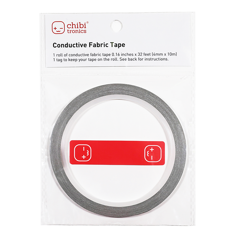
- Conductive Fabric Tape
- Launchpad Battery (or CR2016 or CR2032 Battery)
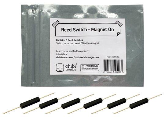
- 1 Reed Switch (magnet on)
- 1 Neodymium disk magnet (preferably with an adhesive backing)
Other Tools & Supplies
- Cricut (smart cutting machine)
- Cardstock
- Vellum
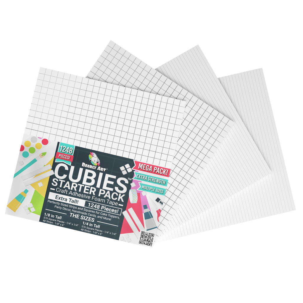
- Bearly Art Cubies (or other foam squares/strips that are roughly the height of your battery)
- 1 piece of acetate (such as this) large enough to cut into a ⅜” W X 8” H strip
- 3 small metal brads
- Double-sided tape
- Scotch tape
- Scissors
Optional
- Printer (if printing the circuit diagram)
- Hole punch or Japanese screw punch & self-healing mat
- Craft Glue
- Art supplies of your choice (ex. gouache paint and the Small Spider and Thread die from Lawn Fawn’s Cute Cobweb set.)
Directions
To follow along with the tutorial, you’ll need a Cricut smart cutting machine. I designed most of this project in Cricut Design Space and used a Cricut Maker to produce each piece.
While you might choose to create your own artwork or add embellishments of your choice, I used Cricut’s drawing feature to sketch my spider and webby parts. I used Cricut’s scoring capabilities to outline the location of each card part, and a fine point blade for the cuts, slots, and holes.
Step 1: Prep Your Pieces
Cut Out Card Parts
The first step in making your own mechanical card is to cut out the parts, by visiting my free project on Cricut Design Space.
Updated 31 January 2026: I’ve also included PDFs of the basic card parts in case you want to make your own artwork.
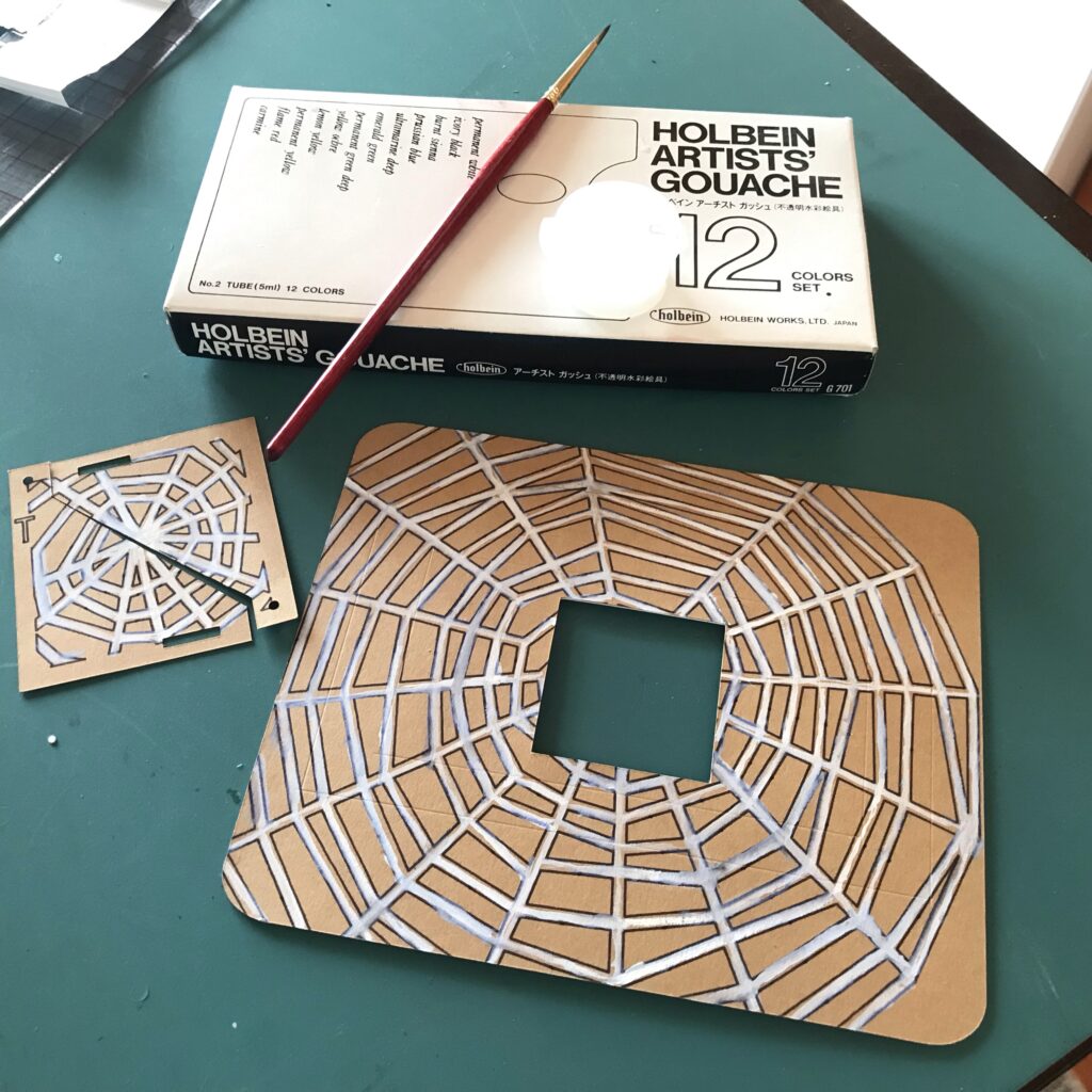
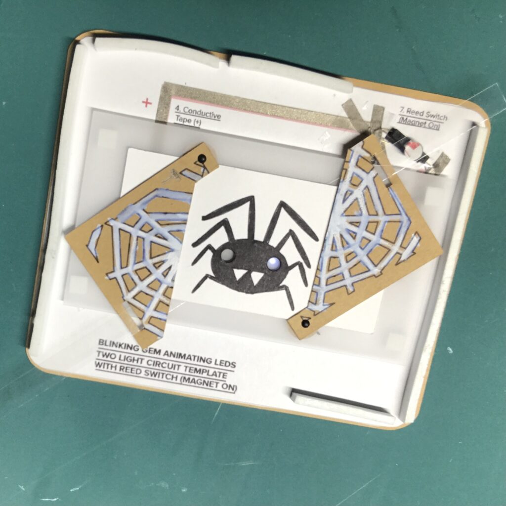
You will need the following parts (Figure 5):
- Card Front (webbed with a slot for the lever and a square cut-out in the center)
- 3 paper washers
- Card Back/Circuit Layer
- Set of Pivoting Doors (webbed, with two holes and slots)
- Lever (made of acetate with a hole in the center)
- Art Layer (a spider). Note: The one depicted below was filled in with a black marker.)
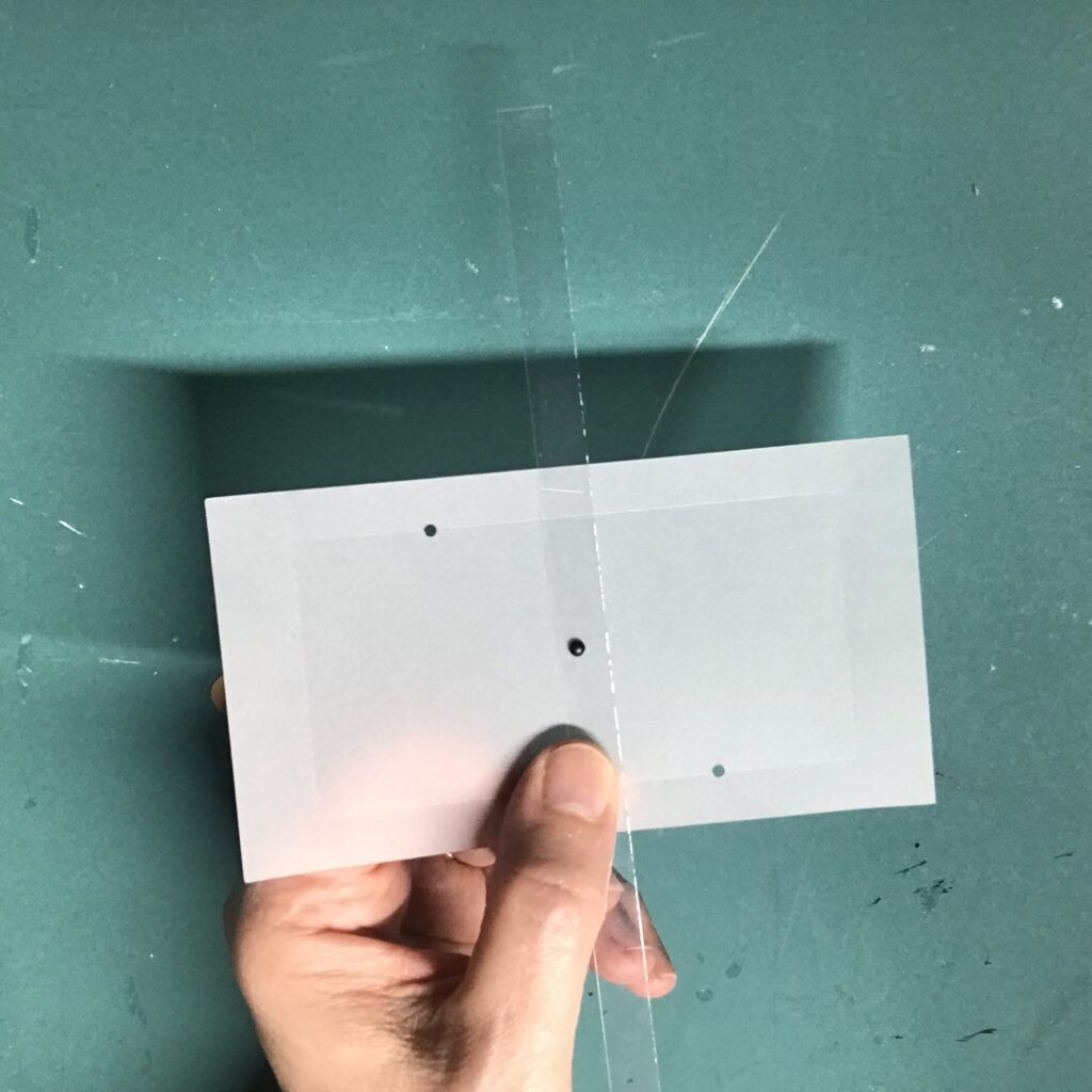
- Vellum Diffusion Layer (scored, with three diagonal holes)
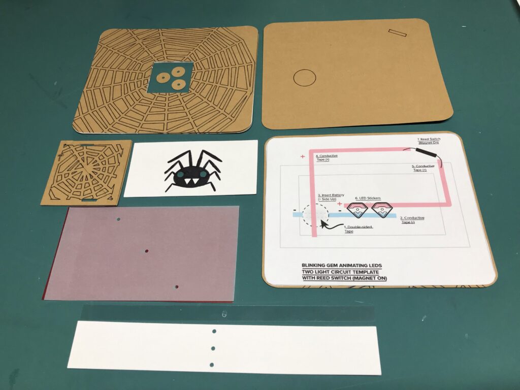
Print Circuit Diagram
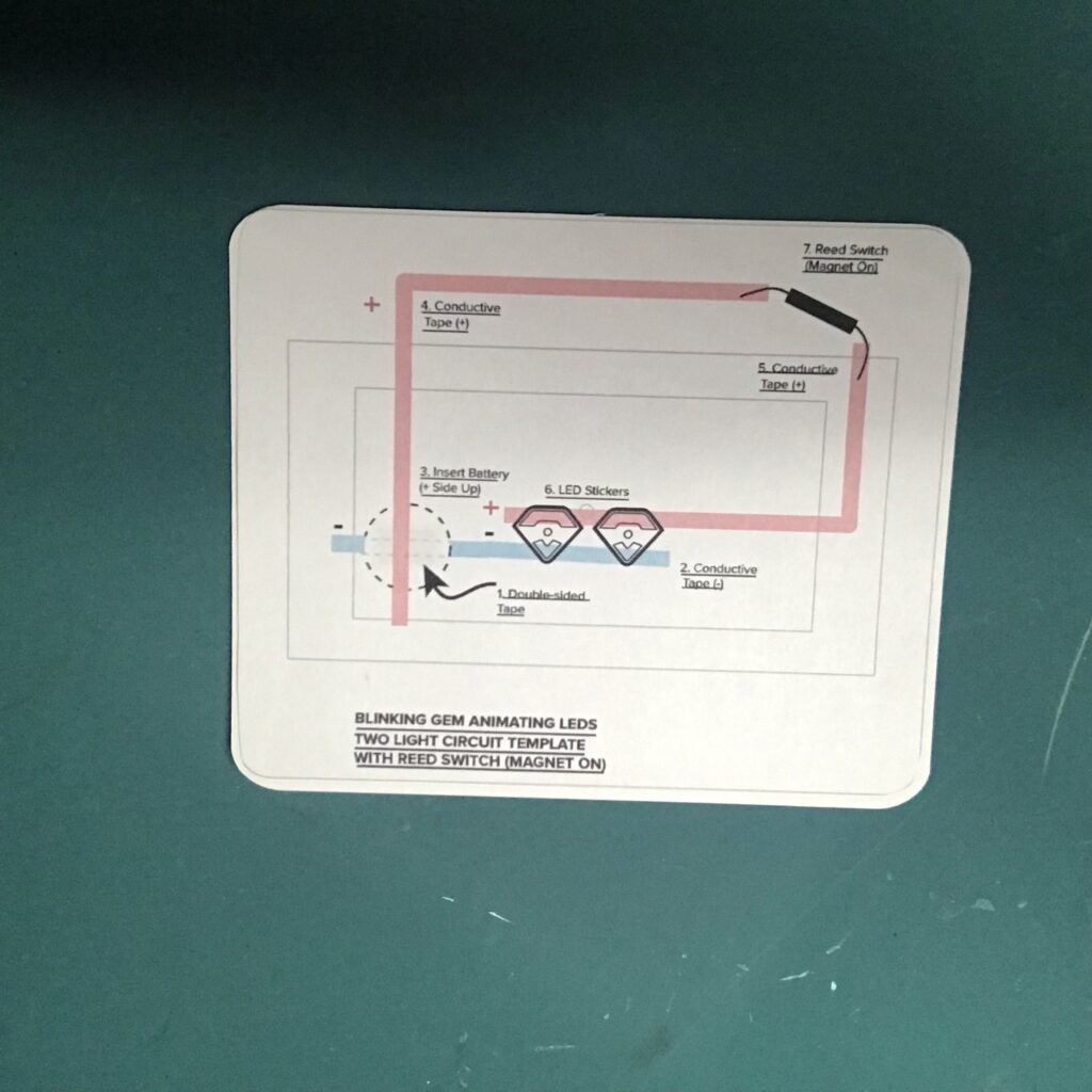
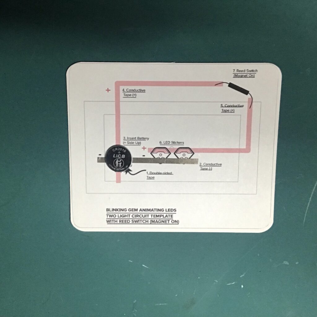
After cutting my card parts, I printed the Circuit Diagram (Image 6).
To make things easier, I used scissors and double-sided tape to adhere a printed copy of the Circuit Diagram on top of the Card Back.
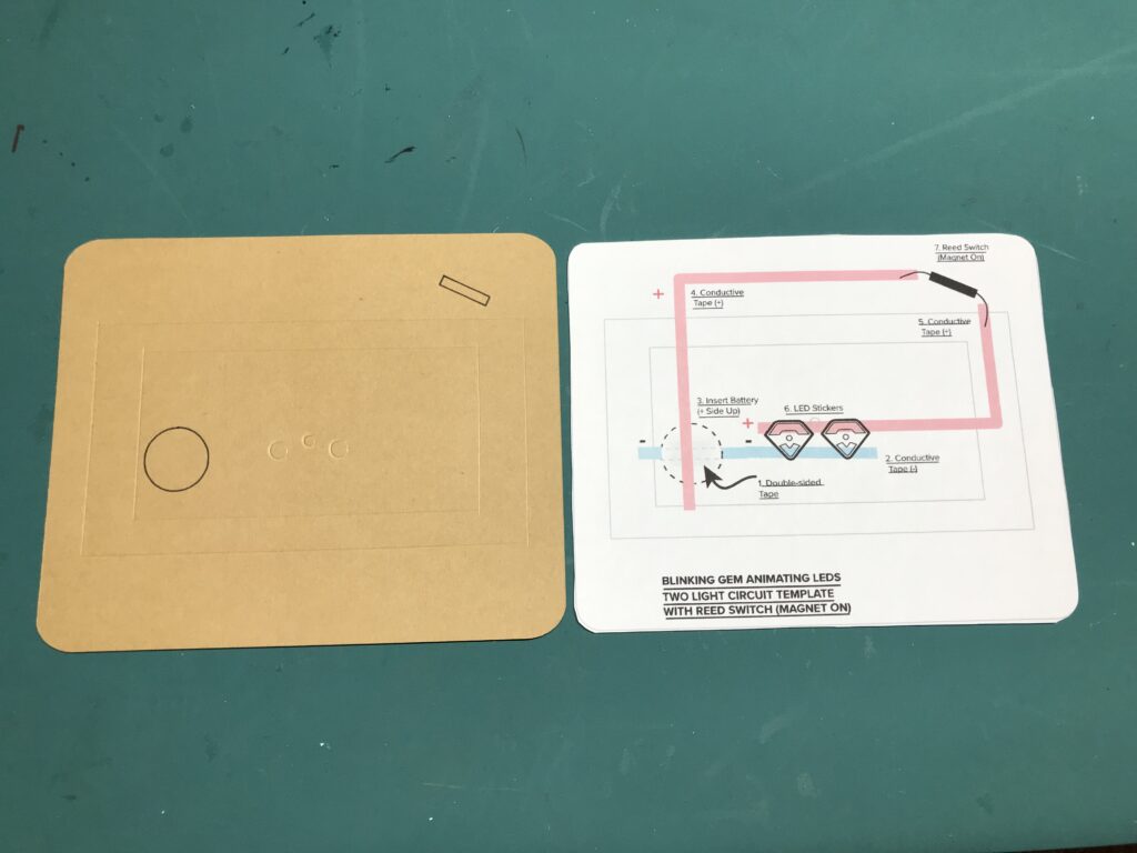
Alternatively, you may simply use the Circuit Diagram as a guide, and build your circuit directly onto the card back. While this tutorial originally used a traditional coin cell battery, a Circuit Diagram that uses the Launchpad Battery is also included.
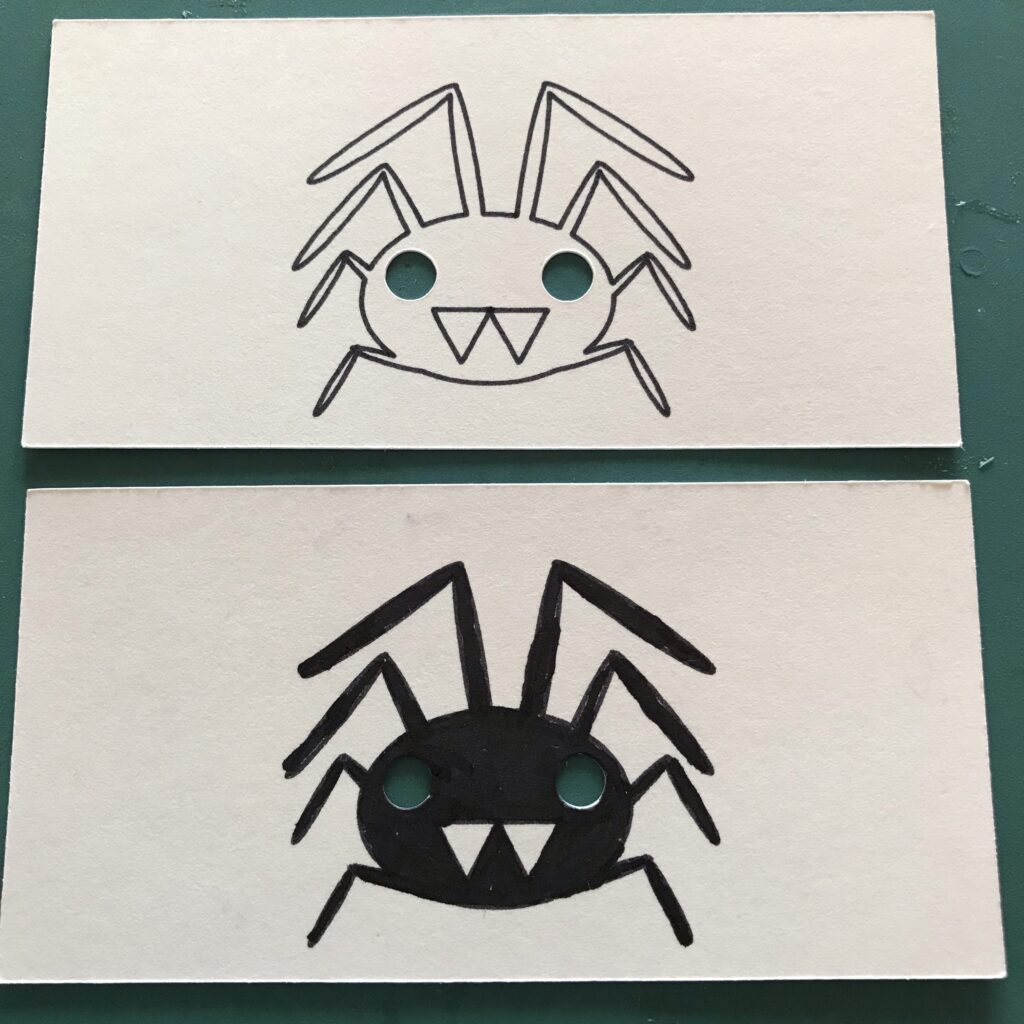
Add Embellishments
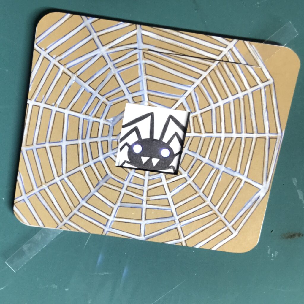
After printing out the circuit diagram, I added embellishments to my spider (Image 7) and card front. I colored my spider with a black marker (Image 7) and painted my card front with white gouache paint (Image 9).
In one iteration, I used the Cricut to cut a spiderweb from a piece of cardstock and glued it onto the card front. This looked nice, but the extra texture near its slot interfered with the smooth movement of the magnet.
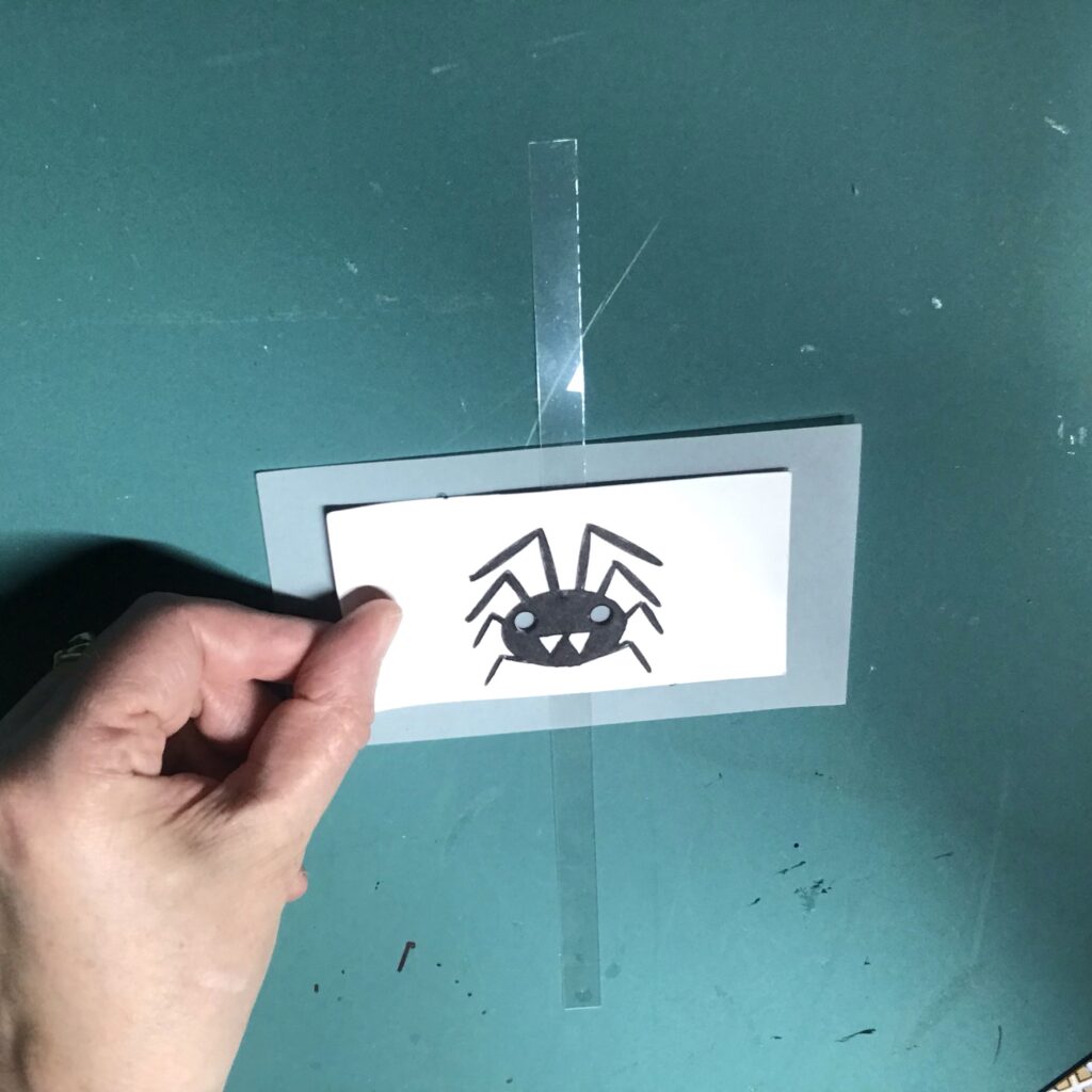
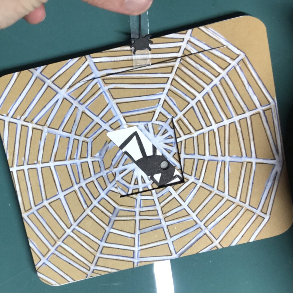
In this early iteration, I also tried using a paper lever (Image 8); but, it required extra steps. Because the paper blocked the light from the spider’s left eye, I had to trace the left eye onto the lever, take the card apart, poke a hole through the lever, and reassemble it.
To make things easier, I suggest using a strip of acetate for the lever, since it’s transparent.
To add visual interest to your card front, you might experiment with markers, inks, or paint (Image 9).
Step 2: Build the Circuit
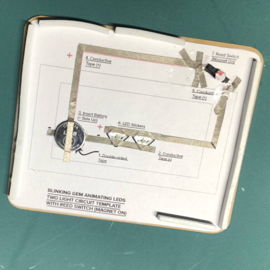
To build your circuit, follow each numbered step on the circuit diagram (Image 10) to ensure correct placement of each component. If you’d like to see exactly how I did this, please watch the video (4:02:00 – 10:02:00).
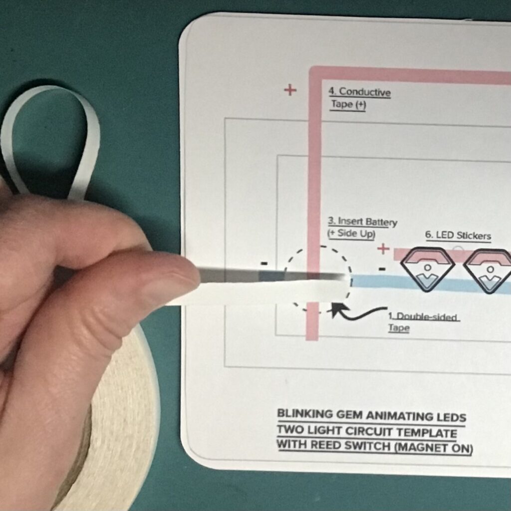
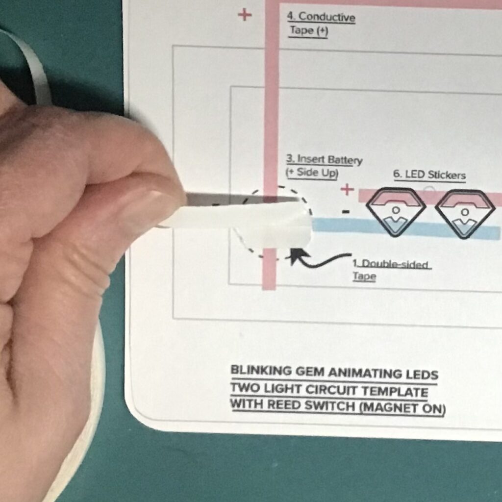
Add Double-Sided Tape
Start by adhering a piece (or two) of double-sided tape directly on top of the battery footprint (Image 11). The tape needs to be wide enough to cover most of the battery outline, because it will be doing double duty (Image 12).
First, it will provide a sticky surface to hold your battery in place. But, it will also be holding a piece of conductive fabric tape in place against the negative side of your battery, to help provide a robust physical and electrical connection for your circuit!
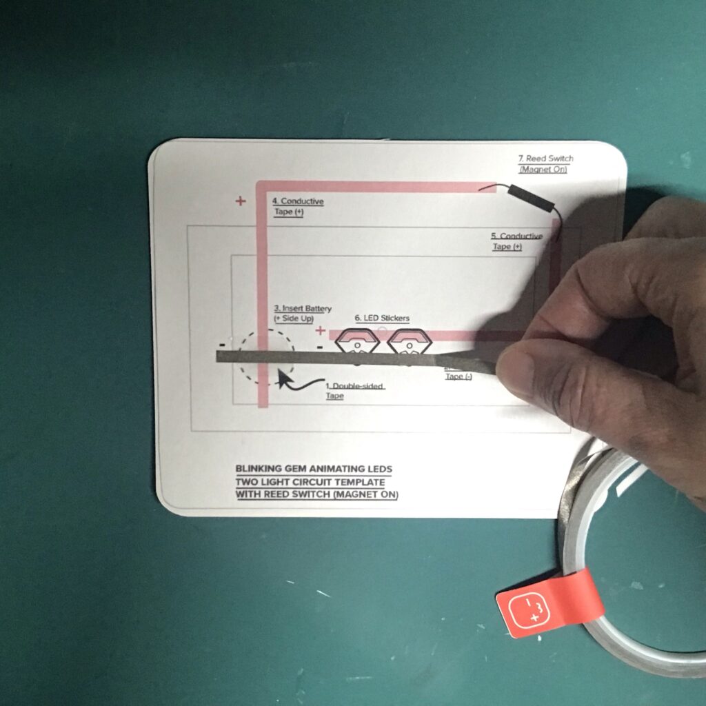
Create Negative Lead
After applying the double-sided tape, create the negative lead of your circuit by placing a piece of conductive fabric tape over the blue footprint on your circuit diagram (Images 13 and 14).
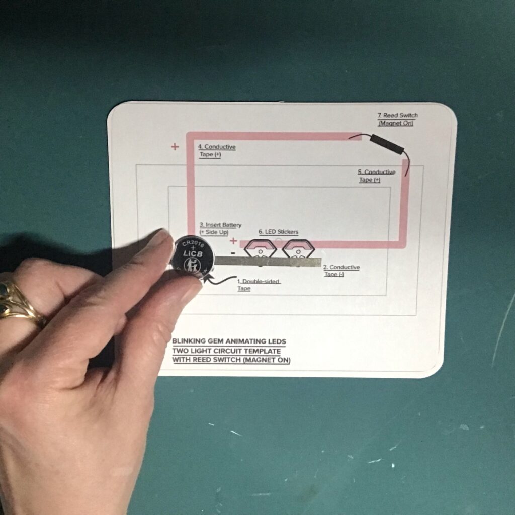
Add Battery
Then, place your battery positive-side up on top of the sticky tape and the negative lead (-) (Images 15 and 16).
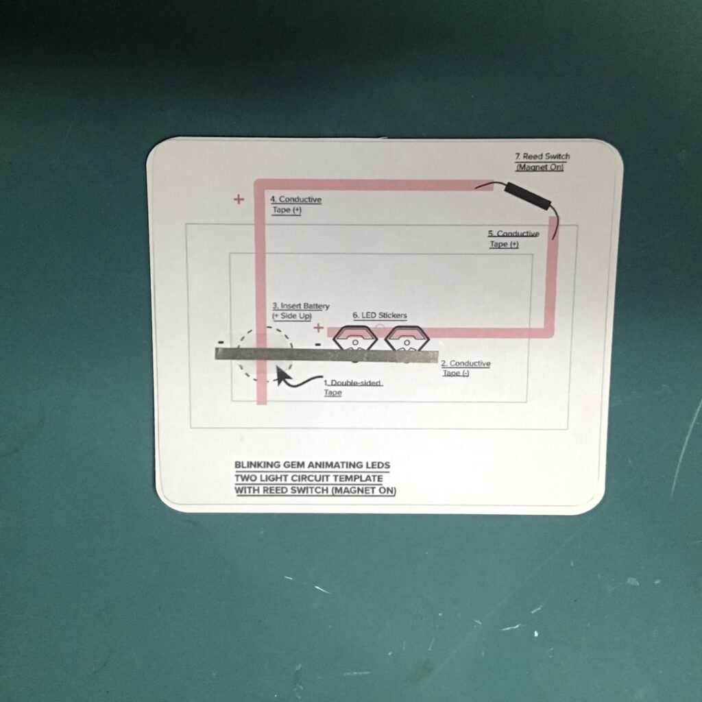
Create Positive Lead
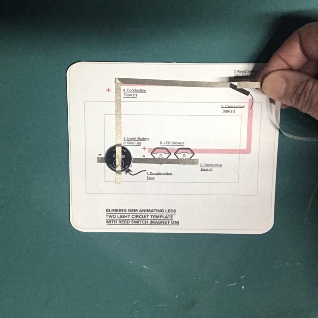
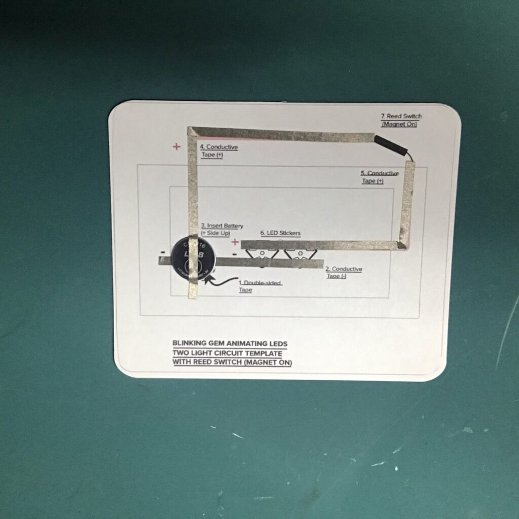
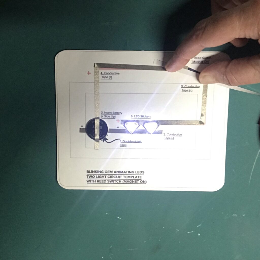
Next, adhere two pieces of conductive tape over the red footprints on your circuit diagram. Notice that you will be leaving a small gap for the reed switch (Images 17 and 18).
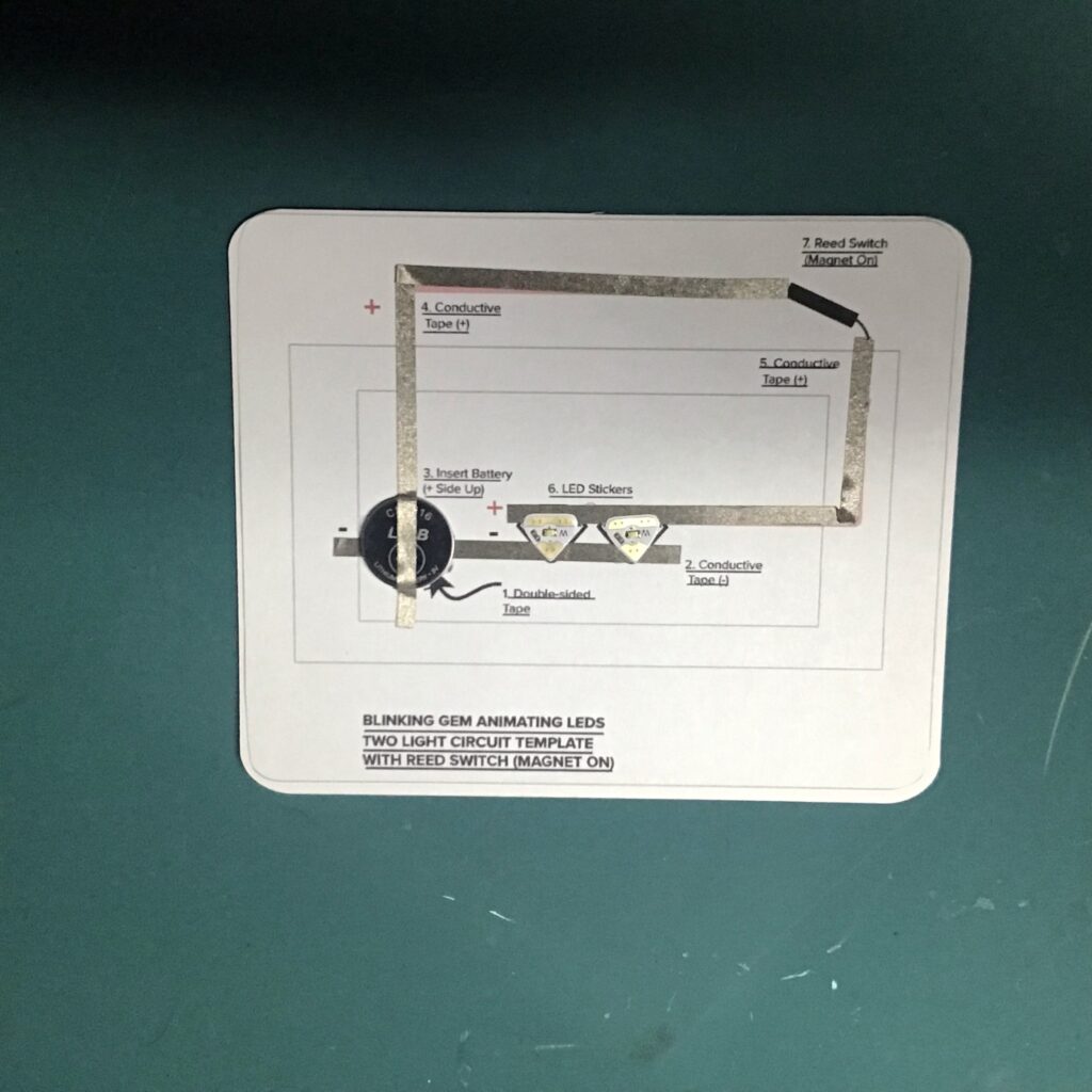
Add LEDs and Test Circuit
Once conductive traces have been applied, adhere the LED stickers within their respective footprints (Image 19). Test your circuit by placing a piece of conductive tape over the gap where your reed switch will be going. Ensure that it is making contact with both parts of the positive lead. If the LEDs light up (Image 20), reinforce them with patches of conductive tape.
Add Reed Switch
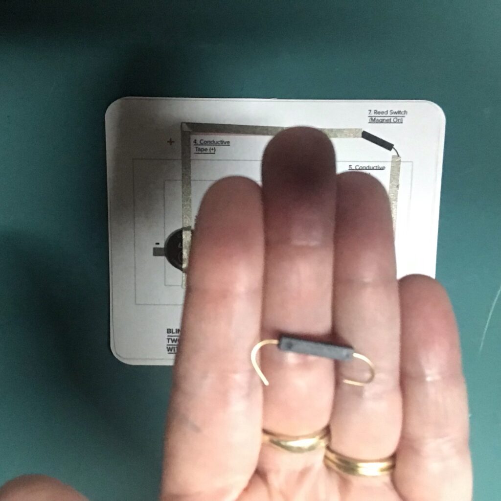
The last part of building the circuit is adding a reed switch (magnet on) in the top right corner of your template. You may need to fiddle with it to determine which of its four sides is most susceptible to the magnet. Usually, that side will come marked with two tiny recessed circles (Image 21).
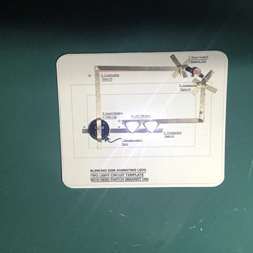
Once you’ve determined which side needs to face the magnet, use conductive fabric tape to secure the legs. Then, place the magnet on top of the reed switch to test the circuit (Image 22).
Tips, Tricks & Call-outs
I usually bend the legs of my reed switch to increase the metallic surface area that will come in contact with the conductive fabric traces. Also, since I don’t want my connections coming loose over time, I like to reinforce this area with clear tape to help keep those reed switch legs anchored.
Step 3: Build Door Mechanism
You will be building the door mechanism on top of a piece of scored vellum. To watch exactly how I do it, watch the video from 2:07:00-4:05:00).
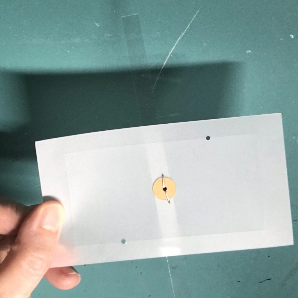
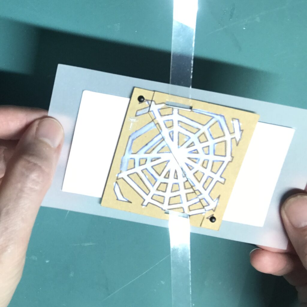
Attach the acetate strip to the center of the vellum piece, by placing a metal brad through it. and securing it with a paper washer (Images 23 and 24).
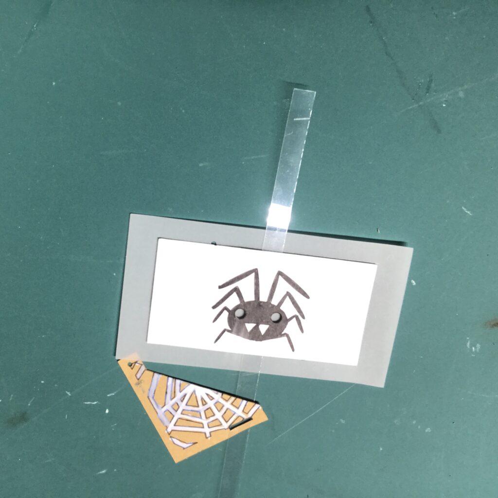
Next, apply double-sided tape to the back side of the spider piece and center it between the embossed outline on the vellum (Image 25). The tape should not impede the movement of the lever.
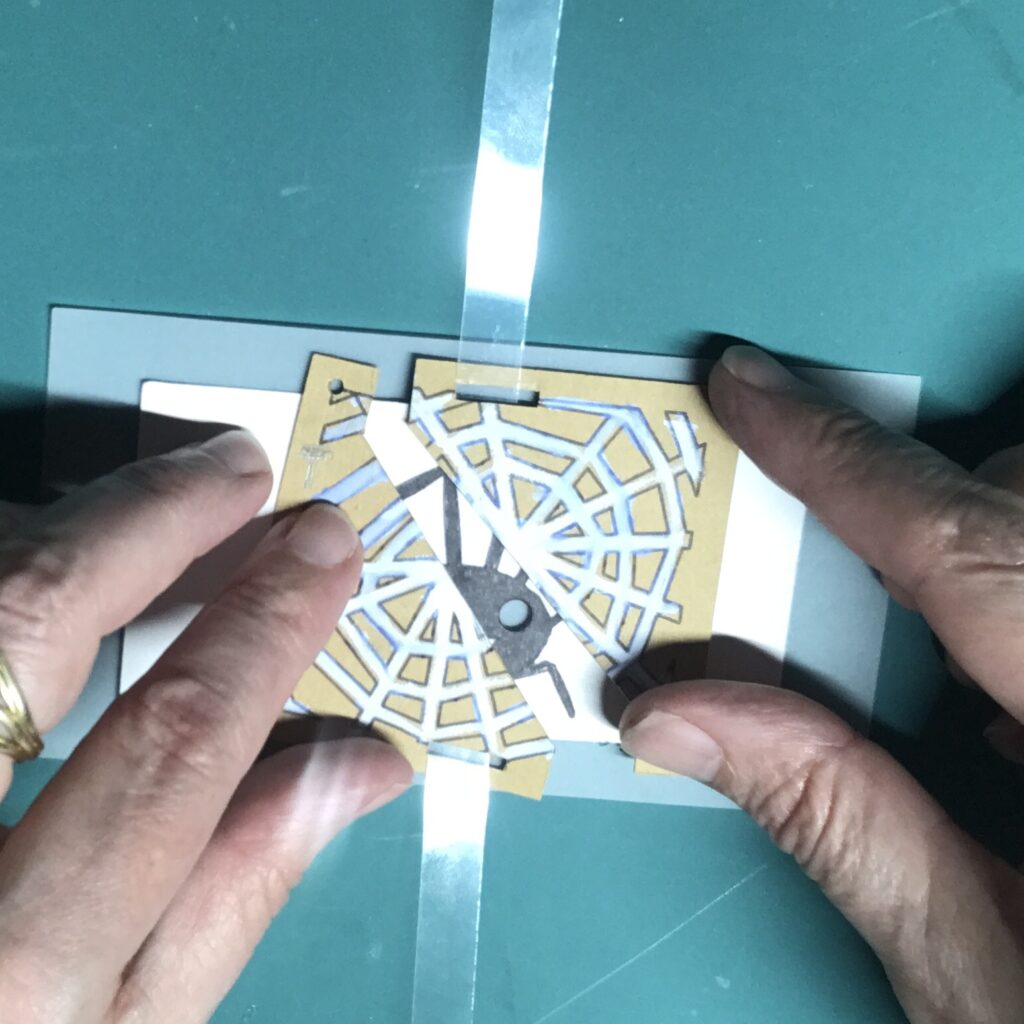
Then, slide each of the diagonal doors onto the lever (Images 26 and 27); keep the “T” oriented upright, so that the pattern on the doors aligns with the card top.
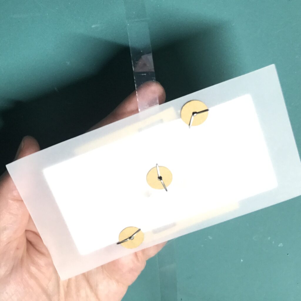
As you did when adding the lever, insert metal brads through the holes in the doors, securing them on the back side with paper washers (Images 28 and 29).
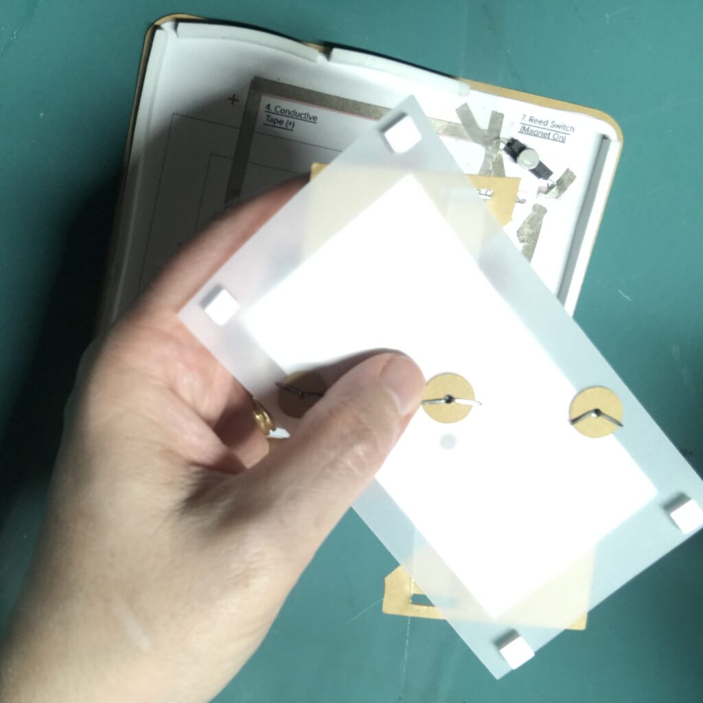
To add a little height, and to better diffuse the light, I added four Bearly Art Cubies (adhesive-backed foam squares roughly the height of the battery) to the back side, leaving the protective backing on (Image 30).
Then test the lever to make sure that everything is moving smoothly.
Step 4: Assemble the Card
To get the magnet adhered in the proper location on the back side of acetate lever, leave the protective backing on the back side of the door mechanism. If you are using a self-adhesive magnet, remove the protective backing from the magnet; if you are not, then apply the adhesive of our choice on top of the magnet.
To adhere the magnet to the lever, open the door mechanism, carefully position it on top of the sticky magnet, and press down.
To ensure that the door works as expected, test it. Then, remove the protective backing from the foam squares on the back side. The holes in the spider eyes should match up with the LEDs on your circuit.
To attach the front of the card with the circuit layer, you’ll need to add foam tape around the edge of the card back, being careful not to impede the movement of the lever (Image 31).
I’m using Bearly Art Cubies, because it comes in squares and strips in two different thicknesses. I’ve used both sizes while making different versions of this card, but I’m opting for the 1/8″ thick strips this time.
Before you remove the protective backing from the foam tape, test the placement of the card front by slipping the magnetic lever through its slot (Image 33). Make adjustments if needed, then remove the protective backing and adhere the front of the card. .
If you don’t like seeing the magnet through the clear lever, you can cover it up (Image 34). You can also trim the overall length of your lever.
Tips, Tricks & Call-outs
It’s okay to trim the bottom of the lever so that it does not protrude from the bottom of your card; just be sure that it remains long enough to thread through the slot in the left diagonal door.
To create the small spider that conceals my magnet, I used the Small Spider and Thread die from Lawn Fawn’s Cute Cobweb set.
Just be aware that adding a decorative element to your lever might impede its movement. With a bit of trial and error, you will find something that works for you.