Spooky Sensor!
In our introductory tutorial, Haunted House Pt. 1: Intro to Pressure Sensors, we show you how to create a haunted house with interactive gravestones, using pressure sensors made from conductive plastic.
In this tutorial, we will teach you how to use a pressure sensor to make the same haunted house light up, one color at a time, mimicking the visible light spectrum of a rainbow.
Tutorial Video
Haunted House Gets a Makeover
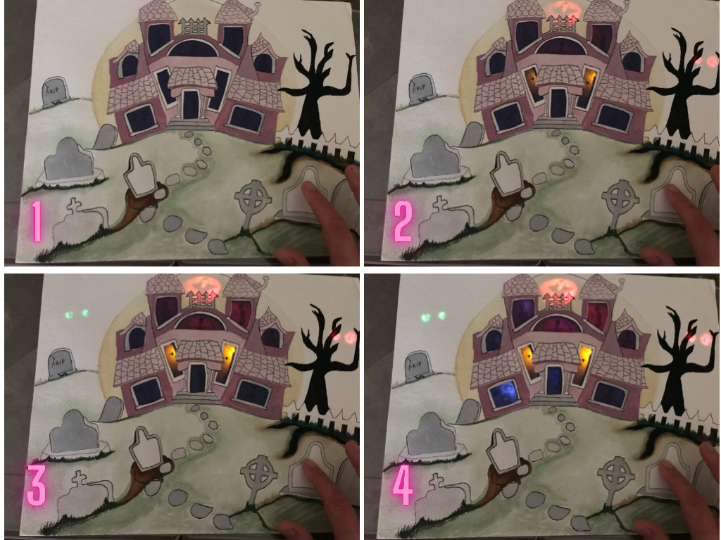
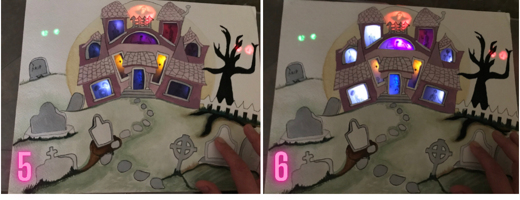
In this tutorial, a follow-up to Haunted House Pt. 1: Intro to Pressure Sensors, our haunted house gets a spooktacular makeover. While it uses the same artwork created in the original, the underlying circuit and resulting special effect are different. Rather than using multiple pressure sensor switches hidden behind the gravestones, the circuit in this tutorial has only one. But, don’t let the simplicity fool you! With a single sustained push of one pressure sensor, the windows in our renovated house will light up one color at a time until the entire house is aglow. As you gradually release the pressure, you’ll notice the lights fade off gently in the reverse order!
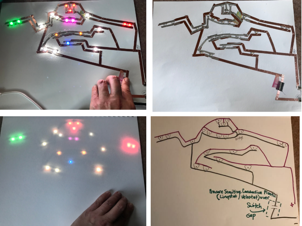
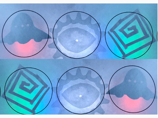
Here is a side-by-side comparison of our haunted house lit by two different circuits, to help you visualize the difference between the two. The original circuit is on the right and the one featured in this tutorial is on the left. Notice that the one on the right is very interactive, with multiple touch points, while the one on the left has a single spot to press.

Pressure Sensitive Conductive Plastic creates special fade in and fade out effects in LEDs within a circuit, because its resistance changes in direct relationship to how hard or soft you press on it. As you press down harder, the resistance in your circuit will decrease, causing more current to flow to your LEDs, making them brighten. As you reduce the pressure, the resistance will increase, causing the current flow to your LEDs to decrease, making the LEDs appear to dim.
This material gets more interesting when you have a bunch of different colored LEDs (such as Circuit Stickers, which have built in resistors) in the same circuit. If you use a piece of pressure sensitive plastic to alter the resistance in your circuit, certain LEDs (red, orange, yellow, and green) will usually light up before other LEDs (blue, pink, and white). This will be true whether the LEDs are arranged in the order of the rainbow (ROYGBIV) or placed randomly. Reds will typically light up first, followed by orange, yellow, green, blue, pink, and white, wherever they may be placed upon a circuit!
Directions
Step 1: Prepare Your Artwork
When creating the haunted house in the original tutorial, we cut windows out of a piece of drawing paper and did the same with a piece of cardboard the same size.

To create the illusion of characters coming to life in the windows as they are lit up, we printed artwork on pieces of white vellum paper, slightly larger than the windows, and taped them to the back of a sheet of purple vellum, to give the appearance of a darkened room. We left our circuit accessible, making it easy to remove for repairs and renovations.
Step 2: Plan & Construct Your Circuit & Switch
Using a clean piece of drawing paper and your haunted house drawing, determine where you want each LED to go. Mark each of those spots with a pencil. It might be helpful if you hold your artwork up to a window with the drawing paper positioned behind it to get a more precise sketch of your window locations. Another way to do this is to connect your original circuit to power and ground, position the drawing paper directly on top, and lightly mark the location of the LEDs.
While planning, it’s helpful to think about the order you want your windows to light up and choose your colors accordingly.
There are many ways to construct a circuit. Your circuit doesn’t need to look like mine for the sequential lighting (rainbow effect) to work, as long as your positive and negative traces never touch one another, and all of your LEDs are positioned within the same parallel circuit.
I used a piece of washi tape as a bridge when an overlap of the positive and negative traces was needed, to prevent a short circuit. Once my circuit sketch was complete, I chose to press my Circuit Stickers down directly onto the paper where I’d marked locations for the LEDs. Then, I laid my positive and negative traces of copper tape/ conductive fabric tape on top. This helped me to be more precise.
When planning your circuit, it’s helpful to sketch out a positive (+) and a negative (-) trace that spans the length of your sketch. It’s also helpful to draw an “X” where you want to create a switch, an area where you will be adding a pressure sensor to close your circuit to light your LEDs.
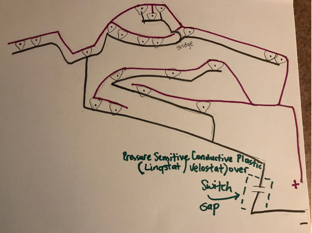
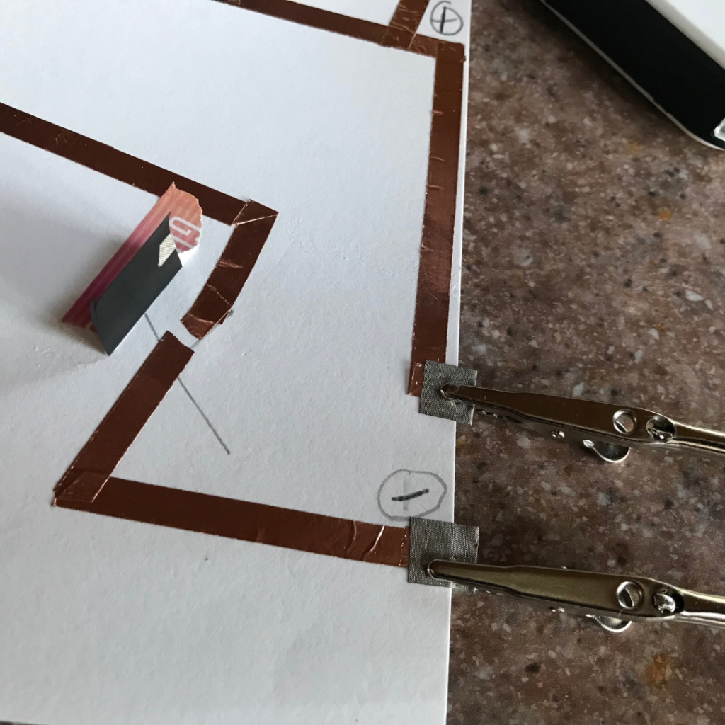
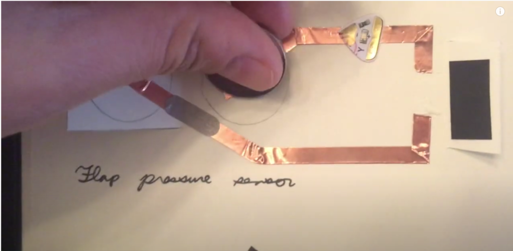
I went about creating my pressure switch by leaving a small gap in my copper tape circuit that I carefully covered with a flap of Pressure Sensitive Conductive Plastic, adhered on one edge with tape. This “flap pressure sensor” type of switch is the second example featured in the video tutorial Chibitronics: 6 DIY Pressure Sensor Circuits. The flap needs to be able to move freely, in case you later discover that an adjustment needs to be made.
Since the conductive plastic is sensitive to pressure, pressing it down firmly over the switch gap not only closes the switch, but it also alters the resistance in the circuit. As you add pressure to a conductive plastic flap by pushing it down over the switch gap, the resistance in the circuit will (in most cases) visibly decrease, resulting in a noticeable increase in the brightness of the LEDs! Of note, I found that a large gap is not as effective as a narrower one.
Step 3: Test Your Circuit & Display Your Art
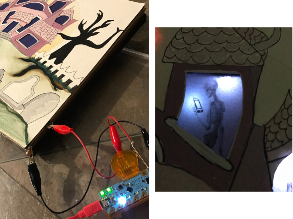
Once you’ve laid down your conductive traces and placed a conductive plastic flap over the gap you left in your circuit, connect your circuit to power and ground to ensure that your connections work, the LEDs are placed where you want them, and the pressure sensor switch is working correctly. I added pieces of conductive fabric tape to the ends of my positive and negative leads so that I could easily clip them with alligator clips and power my artwork with a Chibi Chip. If you don’t have a Chibi Chip, but you like the idea of powering your project through USB, you may want to check out the USB Powered Paper Circuits: An Alternative to Coin Batteries tutorial. Alternatively, you can use two 3V coin cell batteries, a couple of magnets, and alligator clips; visit this Variable Power Supply tutorial to learn more.
Once you’ve connected your circuit to power and ground, you should be able to press down on the resistive plastic flap and see the LEDs light up in this order (red, orange, yellow, green, blue, pink, and then white). If you are experiencing too much resistance in your blue, pink, and white LEDs, the pressure sensitive plastic that you are using may not be conductive enough. One way to test out this theory is to place a piece of copper tape over the switch gap and see if the lights all turn on at the same time. If they do, then the issue may be that the resistive plastic you are using has too much resistance. If that doesn’t solve the problem, it’s possible that your circuit might need more power; this is more likely to happen if your circuit has been constructed with conductive fabric tape, as it has more resistance than copper tape. Another thing to try is placing a small piece of craft foam under your artwork and over the switch gap, to add more concentrated pressure to the switch site.
When preparing the haunted house for display, I created a taped hinge at the top of my piece rather than adhering the art layer permanently to the circuit layer.
Tips, Tricks & Call-outs
The Pressure Sensitive Conductive Plastic sold by Chibitronics is more conductive than many of the resistive plastic products on the market, because it contains more carbon. When testing my circuit the first time, I discovered that the blue, pink, and white LEDs were encountering too much resistance, resulting in a much dimmer LED effect than I wanted, even with firm pressure. When I swapped out the standard resistive plastic that I had been using, substituting a square of Chibitronics version of the conductive plastic, the LEDs brightened up considerably. I did, however, discover that by sandwiching a piece of the less conductive plastic between the copper tape switch and the more conductive Chibitronics flap that I got a wider range of brightness values (and a more dramatic fading effect) when pressing on the switch than using only the more conductive material. (This effect is similar to what happens in the DIY Pressure Sensor example in Chapter 5 of the Circuit Sticker Sketchbook (Template 5).
Compare the Circuits
The circuit on the left, the one that lights up in a sequence, is a parallel circuit with a single switch, a flap pressure sensor, that interrupts the negative lead in its unpressed state.
The circuit on the right, a more complex parallel circuit, has multiple flap sensors disrupting the negative leads of several different circuit paths. While each switch connects to at least one LED, multiple switches may be triggered at any given time.
Better Understand How the Rainbow Effect Works
How bright an LED shines depends upon how much electricity, known as current, is running through the light. If the light is off, then no current is running through it. To get current to flow through the LED, there needs to be enough voltage powering the circuit to meet the threshold for your LED, which is known as its forward voltage. If you look at the table below, you will notice that forward voltage is lower for red, orange, yellow, and green LEDs, and higher for blue, pink, and white.
LED Forward Voltage
(Exact values will vary depending upon the manufacturer.)
| LED Color | Voltage Range |
| Red | 2.0 – 2.8 V |
| Orange | 2.0 – 2.5 V |
| Yellow | 2.0 – 2.5 V |
| Green | 2.2 – 4.0 V |
| Blue | ~3 V |
| Pink | ~3.2 V |
| White | ~3.3 V |
One easy way to control the voltage powering your LED is to use a resistor in the circuit. The higher the resistor, the lower the voltage going to your light. Given the same resistor value, circuits using LEDs with a higher forward voltage (blue, pink, and white) will have less total current and be dimmer.
In this project, the pressure sensor is used as a resistor that changes its resistance when pressed. When I press down gently on the conductive plastic, the resistance slowly decreases and the voltage slowly increases. At first, the voltage is so low that none of the lights turn on. As I press harder, the red and orange lights shine first. As I press down even harder, the other colors show up in order of their forward voltage (yellow and green, then blue, pink, and white).
Related Project Tutorials

Haunted House Pt. 1: Intro to Pressure Sensors
In this tutorial, we’ll teach you how to use flaps of pressure conductive plastic to add gentle fading effects to your paper circuit projects. When you touch the gravestones of this haunted house, different LEDs will gently fade on and off.
Shadows & Silhouettes
In this activity, you’ll make swatch cards to experiment with different paper and light effects and ponder possibilities for using the properties of both for art and engineering.
6 DIY Pressure Sensor Circuits
This video tutorial demonstrates a variety of pressure circuit techniques using Pressure Sensitive Conductive Plastic (velostat/ linqustat).
Similar Posts You Might Enjoy
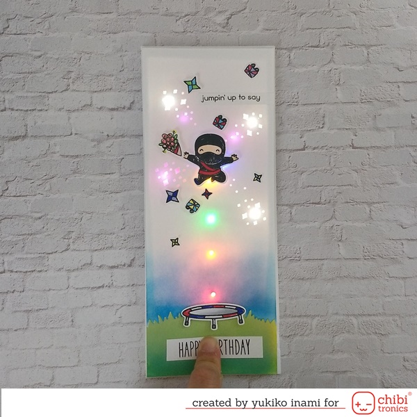
Jumpin’ Up to Say “Happy Birthday!”
Learn how to make a pressure sensor that lights up fireworks in a staggered burst of color!
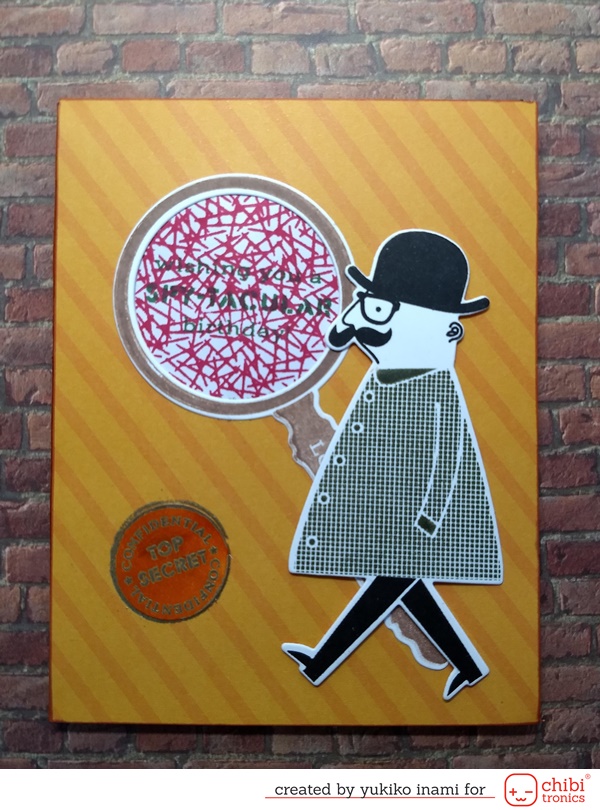
Private Eye With a Secret Message
A top secret message becomes clear with a little help from Pressure Sensitive Conductive Plastic.
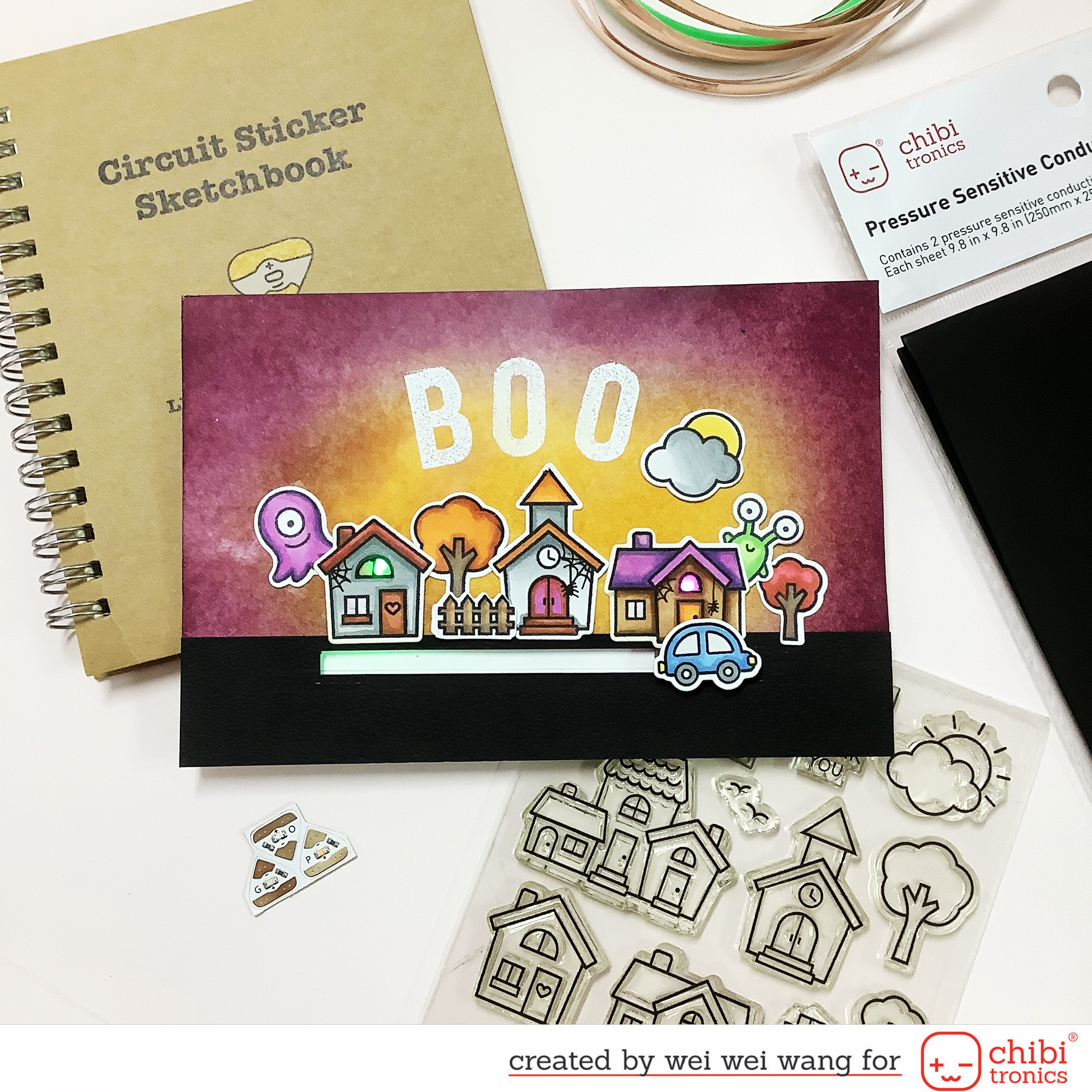
Halloween Light Up Card
Add a gentle fade in and fade out effect with Pressure Sensitive Conductive Plastic.
Featured Products
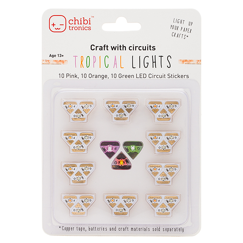
Circuit Stickers
Chibi Lights
$35.00

Copper Tape
Copper Tape
$10.00
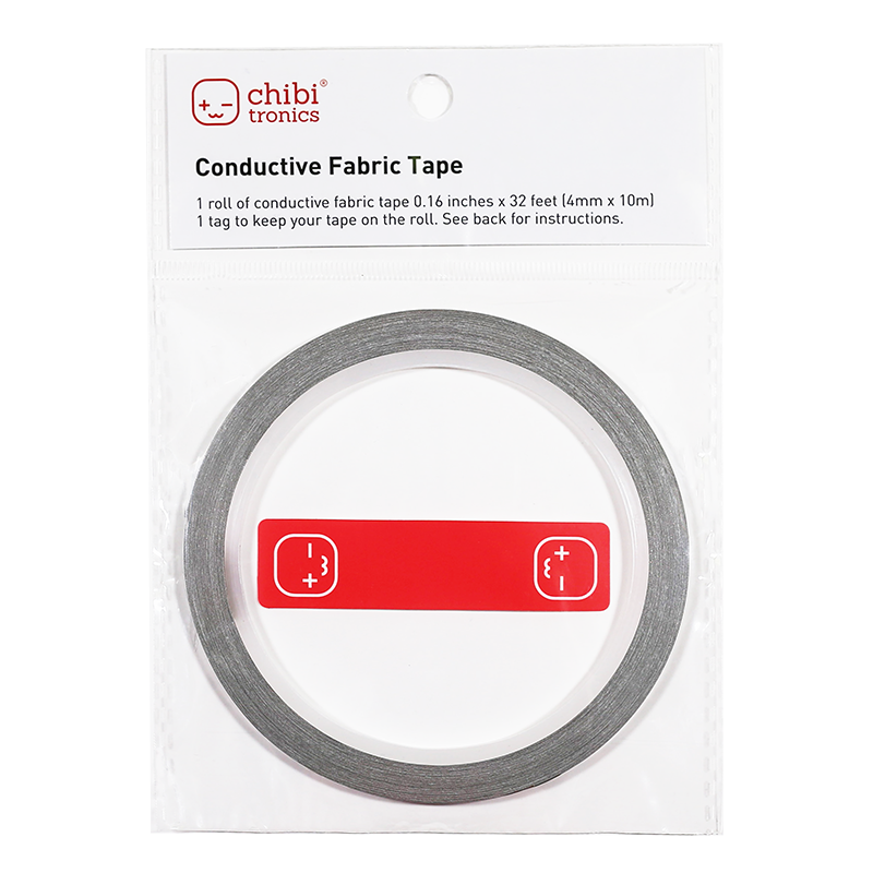
Conductive Fabric Tape
Conductive Fabric Tape
$10.00

Pressure Sensitive Conductive Plastic